ProVision 3 Installation Manual
8100-35521-00
Rev. A0
Leidos Security Detection & Automation, Inc.
–
Proprietary
Page 85 of 119
© 2020 Leidos. All rights reserved
12.2
Power Cable Routing
1.
After performing the pre
–
power-up checks, plug the power cord into the power input receptacle on
the scanner.
2.
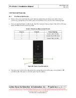
If the power input receptacle is located at the
lower position, route the cord downward along the edge
of the entrance/exit cover.
3.
Lift the cable clips referenced in Section 11.34 and slide the cord under each clip and into the
rubberized portion of the clip.
4.
Ensure the power cord has as small a loop or bend as possible but not to the point where there is stress
on the plug/power input receptacle.
5.
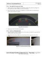
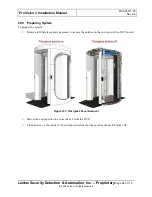
If the power input receptacle is located at the
upper position, route the cord upward along the edge of
the entrance/exit cover, as shown in the following figure.
6.
Lift the cable clips referenced in Section 11.34 and slide the cord under each clip and into the
rubberized portion of the clip.
7.
Ensure the power cord has as small a loop or bend as possible, but not to the point where there is
stress on the plug/power input receptacle.
8.
Continue routing the cable up to the top of the scanner and secure to the closest screw on the top with
a plastic P-clip.
12.3
Scanner Power-Up and Warm-Up
1.
Plug the power cord into a wall outlet or other specified power source, then press the portion of the
power switch labeled
“
I
”
to turn on the scanner. Once the switch is turned on, the ASCU fans emits
an audible noise for a few moments and then quiet down.
2.
Verify the lights inside the scanner turn on.
3.
Make a note of the time. You need to let the scanner warm up for at least 30 minutes before
performing the scanner calibrations described later in Section 12.6.
This warm-up period is necessary to allow all electronics to reach operating temperatures before the
scanner calibrations are performed. Proceed to the next section to set the date and time.

