Version 2.1
09/2010
NOVOLAS Basic AT
Installation
37
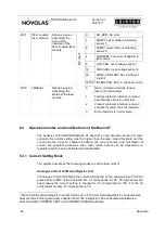
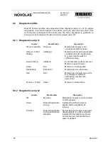
5.5.1 Time scheme for typical Integration
Configuration
Procedure
Cmode: 2
1. Interlock closed
Rmode: 0
2. Interlock Test finished
Gmode: 3
3. Gate active
Activation: 2
4. Ready signal active
Keyswitch: Enable
5. Trigger Status change
System running
Interlock
Input
Interlock Test
Internal
Gate
CIO Input
Trigger
CIO Input
Analog In
CIO Input
Laser Current
Ready Signal
CIO Output
closed
open
on
off
Active
Inactive
10 V
0 V
100 A*
0 A
t
in
=100 ms
* 150 A for Linebeam
Active
Inactive
Active
Inactive
Laser ON
Laser Off (as
Interlock is open)
start -up
phase
Laser ON
Figure 14: Signal Scheme for a typical integration


