Version 2.1
09/2010
NOVOLAS Basic AT
Operation
41
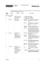
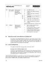
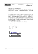
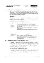
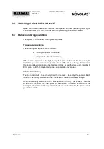
The table below gives an overview of the available registers. The individual meaning
is described in the following chapters
Register
Index
Name
Function
Units
Value range
Read / write registers
0
CMode
Sets the way the
set current will be
determined
-
0 = digital current setting
1 = profile current setting
2 = analogue current setting
Bit 0 reset
(default)
If a pyrometer is connected, the
measured values are being
used.
Bit 0 set
If a pyrometer is connected, the
calibrated values are being
used.
Bit 1 reset
(default)
Current is set as defined in
analogue or digital current set.
1
Rmode
Closed loop
control mode
-
Bit 1 set
Two-Point temperature closed
loop control is active. Current
will switch between threshold of
the laser diode and the analogue
or digitally defined current max.
Bit 0 reset Gate signal of customer IO is
being ignored.
Bit 0 set
(default)
In addition to the other
conditions, the gate signal of the
customer IO needs to be active
in order to allow for emission of
laser light.
Bit 1 reset Ready Signal is active, if laser
unit is ready. Interlock does not
need to be closed.
2
Gmode
Regulates the
control
characteristics of
the inputs and
outputs. Bit coded.
See description.
-
Bit 1 set
(default)
Ready Signal is only active, if
laser unit is ready and Interlock
is closed and secured.
0:
Laser off/ profile stopped
0->1:
Laser switches on or profile is
started
3
Activation
Defines the
conditions for the
laser to be
switched on or off
or, if in profile
mode, for a pulse
train to be
triggered.
-
2 (default): Laser will switch on or profile will
be started if the trigger signal
switches from inactive to active


