NOVOLAS Basic AT
Version 2.1
09/2010
50
Operation
6.6
Diagnostics LEDs
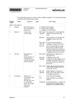
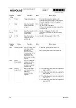
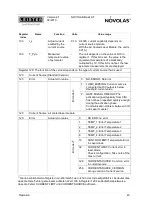
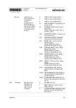
Most AT System modules are equipped with two diagnostic lamps L1+ L2 for system
diagnostics. . Each lamp consists of two LEDs, each with green and red colour. If the
red and green is activated at the same time, the colour impression is yellowish. To
achieve a correct analysis, the lamp has to be viewed under 90°.
6.6.1 Diagnostic Lamp L1
L1 state
Module State
Description
Off (L2 is also off)
No power
Modules 24V supply is not
connected or without power.
1xGreen, 1xRed
blinking
Initializing
Module waits for all environmental
conditions to meet requirements.
E.g. laser module waits for
sufficient cooling
Green blinking
Initialized
Environmental conditions are met.
Module is ready for start.
Green
Run
Module is in working state.
Red blinking
Shut down
Module has been shut down.
Red
Error
Module has encountered an error.
E.g. cooling not sufficient,
overheating, low flow rate,
overcurrent.
2x Green, 1x Red
Reset
Module is in Reset State
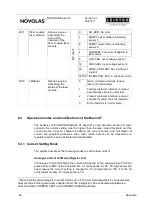
6.6.2 Diagnostic Lamp L2
L2 state
Module State
Description
Off
No power
Modules 24V supply is not connected
or without power.
Green
Powered Application
running
Indicates the intrinsic power is
applied and the application is
running.
Yellowish
Powered Application
running and module
activated
Normal state but module is an power
delivering state. E.g. laser modules
indicate that the interlock is closed,
Current sources indicate that main
power is applied.


