background image

10

Plataforma de juegos modelo 5010 • 09-1214

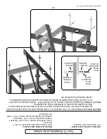
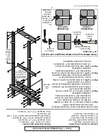
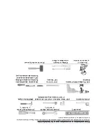
Artículos necesarios para esta fase:

Herrajes necesarios para esta fase:

Perno hexagonal * 5/16" x 2-1/4" * Necesita 4

Tuerca en 

T c/púas * 5/16" * Necesita 4

Arandela reguladora * 5/16" x 11/16" * Necesita 4

Arandela de seguridad de dientes internos * 5/16" - 19/32" 

OD * Necesita 4

K2 * Larguero de piso * Necesita 2 

Paso 12

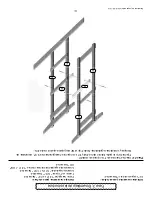
: Inserte 2 tuercas en T

 con púas en cada K1.


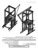
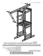
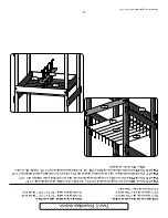
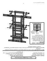
Fije los K2 a la parte interior de los E2s y E1s con pernos hexagonales de 2-1/4", arandelas de 

bloqueo y arandelas reguladoras. Nota: Fije el K2 al agujero superior de los E1s.

Fase 3: Ensamblaje de la estructura

K2

K2

E1

E1

E2

E2

Summary of Contents for 5010

Page 1: ... Manual FAQ s Assembly Instructions Warranty Information Play Deck Wooden Playcenter 2010 Model 5010 Manufacturer Backyard Discovery 3001 North Rouse Pittsburg KS 66762 Made in China INS 5010 01 Rev 11 17 2009 ...

Page 2: ...t in the warranty being void and or safety violations that could result in serious injury This manual contains helpful information concerning Assembly Preparation Installation Procedure and Required Maintenance Always keep the safety of your children in mind as your play structure is being built and as your children play on the set Before your children play on the set please review the Operation I...

Page 3: ...al platforms and slides out of direct sunlight to reduce the likelihood of serious burns A slide that faces north will receive the least direct sunlight 9 Separate active and quiet activities from each other For example locate sandboxes away from swings or use a guardrail or barrier to separate the sandbox from the movement of the swings Suggested Playground Surfacing Playground equipment should n...

Page 4: ...e swing area the total Unit capacity is outlined in the assembly section of instruction manual The maximum fall height and recommended play area is also available on the assembly manual for the specific unit 2 On site adult supervision is required 3 Instruct children not to walk close to in front of behind or between moving swings or other moving playground equipment 4 Instruct children to sit in ...

Page 5: ...and chains should be removed and replaced if excessive wear is found 6 For rusted areas on metallic members such as monkey bars hand supports brackets etc Sand and repaint using a non lead based paint meeting the requirements of Title 16 CRF Part 1303 7 Inspect wood parts monthly The grain of the wood sometimes will lift in the dry season causing splinters to appear Light sanding may be necessary ...

Page 6: ...eter of stationary equipment such as climbers and slides However because children may deliberately jump from a moving swing the shock absorbing material should extend in the front and rear of a swing a minimum distance of 2 times the height of the pivot point measured from a point directly beneath the pivot on the supporting structure X3 4 This information is intended to assist in comparing the re...

Page 7: ...for more information 8 What is the best way to get started assembling the playset Backyard Discovery recommends taking all the parts out of the boxes and arranging them by part number before you begin any assembly This will not only allow faster assembly but will also identify any parts that may be missing or damaged so they can be replaced before assembly If parts are missing or need replacement ...

Page 8: ...the right hardware in the correct place when assembling the unit you can compare the hardware to the hardware identification page NOTES 1 Do not include the bolt head when measuring the length of a bolt 2 Include full length of the deck screw when measuring 60 70 3 80 90 120 110 130 140 150 100 20 3 4 1 1 2 10 1 4 5mm 4 5 2 50 40 30 19 5 5 92 9 4 2 85 Recommended Saftey Zone Play Area 7 5 2 26 2 8...

Page 9: ...e not included in the playset purchase Level 24 Open end Wrenches Nut drivers 7 16 9 16 Tape Measure 3 8 Drive Ratchet 9 16 std sockets Claw Hammer 9 16 deep sockets 3 8 Cordless Drill or Electric drill 1 8 5 16 Drill attachments 3 8 drill bits Phillips head screw 3 8 Socket Driver Torque head screw An Adult w an Phillips Straight Blade Rubber Mallet Optional Adult helper screw drivers ...

Page 10: ... 8 Phase 2 Frame Assembly 9 Phase 3 Frame Assembly 10 Phase 4 Frame Assembly 11 Phase 5 Floor Assembly 12 Phase 6 Angle Brace Assembly 13 Phase 7 Wall Assembly 14 Phase 8 Tent Assembly 15 Phase 9 Tent Assembly 16 Phase 10 Hand Grip Assembly 17 Phase 11 Ladder Assembly 18 Phase 12 Ladder Assembly 19 Phase 13 Stake Assembly 20 Phase 14 ID Plate Assembly 21 ...

Page 11: ...del 5010 09 1209 Front Parts Not Shown P3 P6 K1 P2 Right Back Left N3 N6 N4 P9s P8s N8 N9 N10 N10 N10 N10 N9 N5 N5 E2 E2 N7 K2 P5 P1 N1 N4 P10 K1 N2 N6 E1 E1 P1 N1 N5 N4 N4 P8s N8 K3 K3 K2 P5 P9s E2 N7 P1 P7 N5 P4 P2 ...

Page 12: ...x 1224 mm 2 Req N1 W100005 Ground Board 5 8 x 5 1 2 x 89 16 x 134 x 2260 mm 1 Req N2 W100006 Top Rail SB 5 8 x 5 1 2 x 54 1 2 16 x 134 x 1386 mm 1 Req N3 W100007 Top Rail MB 5 8 x 5 1 2 x 54 1 2 16 x 134 x 1386 mm 1 Req N4 W100008 Arch Top Rail 5 8 x 5 1 2 x 30 16 x 134 x 762 mm 2 Req N5 W100009 Base Board 5 8 x 5 1 2 x 30 16 x 134 x 762 mm 2 Req N6 W100010 Wall Rail 5 8 x 5 1 2 x 29 7 8 16 x 134 ...

Page 13: ...pport 5 8 x 3 1 2 x 30 1 4 16 x 86 x 766 mm 1 Req P4 W100016 Floor Rail 5 8 x 3 1 2 x 30 16 x 86 x 762 mm 1 Req P5 W100017 Wall Rail 5 8 x 3 1 2 x 29 7 8 16 x 86 x 758 mm 2 Req P6 W100018 Floor Support 5 8 x 3 1 2 x 29 7 8 16 x 86 x 758 mm 1 Req P7 W100019 Swing Block 5 8 x 3 1 2 x 29 7 8 16 x 86 x 758 mm 1 Req P8 W100020 Floor Board 5 8 x 3 1 2 x 27 1 8 16 x 86 x 690 mm 6 Req P9 W100021 Wall Boar...

Page 14: ...8 ZWS11 8 Wood Screw 8 x 1 1 8 40 ZWHS3 4 Modified Truss Washer Head Screw 8 x 3 4 18 ZTN Spike T Nut 5 16 58 ZFW5 16 Fender Washer 5 16 x 11 16 95 ZFW5 16SAE Flat Washer 5 16 SAE 11 16 OD x 11 32 ID 5 ZLW5 16 Internal Tooth Lock Washer 5 16 19 32 OD 100 ZPTH1 Phillips Truss Head Bolt 1 4 20 x 1 5 ZPBN3 4 Phillips Barrel Nut 1 4 20 x 3 4 8 ZSB1 Step Bolt 1 4 x 1 5 NOTE QUANTITIES INCLUDE EXTRA HAR...

Page 15: ...E TO SCALE BUT SMALL VARIATIONS ARE NORMAL ZHB21 4 5 16 x 2 1 4 Hex Bolt ZHB2 5 16 x 2 Hex Bolt ZHB11 2 5 16 x 1 1 2 Hex Bolt ZHB11 4 5 16 x 1 1 4 Hex Bolt ZHB3 4 5 16 x 3 4 Hex Bolt ZFW5 16 5 16 Fender Washer ZLS2 15 16 x 2 Lag Screw ZWS14 11 2 14 x 1 1 2 Wood Screw ZWS11 2 8 x 1 1 2 Wood Screw ZLW5 16 5 16 Internal Tooth Lock Washer ZPTH1 1 4 20 x 1 Phillips Truss Head Bolt ZPBN3 4 1 4 20 x 3 4 ...

Page 16: ...o the two outer holes of N3 Insert 3 4 hex bolts lock washers and fender washers into the two outer T nuts of N3 Step 3 Attach N6 to the top of the E2s below N3 with 2 hex bolts lock washers and fender washers Step 4 Attach P5 to the middle of the E2s with 2 hex bolts lock washers and fender washers Step 5 Attach N7 flush to the bottom of the E2s with 2 hex bolts lock washers and fender washers Ph...

Page 17: ...N2 with 2 hex bolts lock washers and fender washers Step 9 Attach P5 to the middle of the E1s with 2 hex bolts lock washers and fender washers Step 10 Attach P7 to the E1s with 1 1 2 wood screws The top edge of P7 should be 27 from the ground Step 11 Insert 2 spike T nuts into the ends of N1 Attach N1 flush to the bottom of the E1s with 2 hex bolts lock washers and fender washers 27 N2 E1 N1 P7 N6...

Page 18: ... 4 Req Fender Washer 5 16 x 11 16 4 Req Internal Tooth Lock Washer 5 16 19 32 OD 4 Req K2 Floor Rail 2 Req Step 12 Insert 2 spike T nuts into each K2 Attach the K2s to the inside of the E2s and E1s with 2 1 4 hex bolts lock washers and fender washers Note Attach the K2 to the top hole of the E1s Phase 3 Frame Assembly K2 K2 E1 E1 E2 E2 ...

Page 19: ...the E1s and E2s with 2 lag screws lock washers and fender washers Step 14 Attach the N5s flush to the bottom of the E1s and E2s with 2 lag screws lock washers and fender washers Phase 4 Frame Assembly P10 P4 N5 N5 Always drill pilot holes when using lag screws Tap the head of the lag screw with a hammer to start the threads into the wood and then use a 1 2 socket to tighten Typical Installation La...

Page 20: ...5 Attach one N8 flush to the top of P4 and the K2s with 1 1 2 wood screws Step 16 Attach the P8s flush to N8 and to the top of the K2s with 1 1 2 wood screws Step 17 Attach the remaining N8 flush to the top of P4 and the K2s with 1 1 2 wood screws Step 18 Attach P6 to the underside of the N8s and P8s with 1 1 8 wood screws Center P6 with the N8s and P8s as illustrated Phase 5 Floor Assembly N8 N8 ...

Page 21: ... Req Fender Washer 5 16 x 11 16 4 Req Internal Tooth Lock Washer 5 16 19 32 OD 4 Req P1 Angle Brace 2 Req Step 19 Attach the P1s angle end to the E1s with 2 hex bolts lock washers and fender washers The angle end should point towards P5 Attach the P1s flat end to N1 with 1 1 4 hex bolts lock washers and fender washers Phase 6 Angle Brace Assembly P1 P5 P1 N1 E1 E1 ...

Page 22: ...all Board 6 Req Step 20 Attach the P9s to the inside of the N6s and the P5s with 1 1 8 wood screws The P9s should be 3 3 16 apart and they should be attached 1 1 4 from the bottom of the N6s Step 21 Attach the N4s flush to the E1s and the E2s with 2 lag screws lock washers and fender washers The N4s should be aligned with the N6s Phase 7 Wall Assembly The N4s should be aligned with the N6s 14 P9s ...

Page 23: ...nt Support 1 Req Step 22 Insert 2 spike T nuts into the top two holes of one K1 Attach P3 to the top of the K1s with 1 1 2 wood screws Step 23 Insert 1 spike T nut into the outside of each N6 Insert 2 spike T nuts into the outside of N2 Attach one K1 to N3 and N6 with 1 1 2 hex bolts lock washers and fender washers Attach the remaining K1 to N2 and N6 with 1 1 2 hex bolts lock washers and fender w...

Page 24: ...Holes 2 Req Tent Top 85 1 2 x 30 1 Req Step 24 Attach the P2s to N2 and N3 with 1 1 2 wood screws Step 25 Place the tent top over P3 and then pull it even on both sides Step 26 Attach the tent top to the inside of a P2 with 3 4 truss screws Pull the tent top tight and then attach it to the inside of the remaining P2 with 3 4 truss screws Phase 9 Tent Assembly P2 P2 N3 N2 P2 P2 P3 P3 ...

Page 25: ... OD x 11 32 ID 4 Req Internal Tooth Lock Washer 5 16 19 32 OD 4 Req Step 27 Pre drill the holes for the hand grips with a 1 8 drill bit The holes should be 56 and 64 from the ground Attach the hand grips to the right E1 and right E2 with 1 1 2 button head wood screws lock washers and flat washers Phase 10 Hand Grip Assembly X35 Y Hand Grip 2 Req E2 E1 Front Right 56 64 ...

Page 26: ...eq N9 Ladder BD 4 2 Req N10 Ladder BD 5 4 Req X21 G Rock 4 Req Step 28 Attach the N9s flush to the top and the bottom of the K3s with 1 1 2 wood screws Step 29 Attach the N10s to the K3s with 1 1 2 wood screws Step 30 Insert one spike T nut into each of the N10s Attach one rock to each N10 with a 1 1 4 hex bolt lock washer and fender washer and a 1 1 8 wood screw Phase 11 Ladder Assembly wood scre...

Page 27: ...Internal Tooth Lock Washer 5 16 19 32 OD 2 Req Step 31 Attach the ladder to the inside of P10 with 1 1 2 wood screws in the top holes Pre drill the two bottom holes with a 3 16 drill bit Attach the ladder to the inside of P10 with 2 lag screws lock washers and fender washers The ladder should be centered on P4 flush with the deck boards Phase 12 Ladder Assembly K3 Front Right P10 ...

Page 28: ...rk the ground and then twist the metal stakes into the ground Leave 2 of the metal stake above the ground Note You may need to use a long screwdriver for leverage Step 33 Pre drill the holes for the stakes with a 5 16 drill bit Attach the metal stakes to N7 and N1 with 1 Phillips truss head bolts lock washers fender washers and 3 4 Phillips barrel nuts Phase 13 Stake Assembly Y41 Metal Stake 4 Req...

Page 29: ...s phase Hardware needed for this phase NOTE KEEP THE STEP BOLTS TO USE WITH THE SLIDE Modified Truss Washer Head Screw 8 x 3 4 4 Req Step 34 Attach the ID Plate to N6 with 3 4 truss screws Phase 14 ID Plate Assembly Y50 LTP Leisure Time ID Plate 1 Req N6 ...

Page 30: ...stated in the applicable Assembly Manual Acts of nature including but not limited to wind storms hail floods excessive water exposure Improper installation including but not limited to installation on uneven unlevel or soft ground Minor twisting warping checking or any other natural occurring properties of wood that do not affect performance or integrity Backyard Discovery products have been desig...

Page 31: ...tativo viento tormentas granizo inundaciones excesiva exposición al agua Instalación inadecuada incluyendo a título informativo más no limitativo la instalación en tierra dispareja desnivelada o poco compacta Torceduras menores deformaciones fisuras o cualquier otra característica natural de la madera que no afecte el rendimiento o la integridad Los productos de Backyard discovery han sido diseñad...

Page 32: ...OS PERNOS CABEZA LISA VÁSTAGO ROSCADO PARA UTILIZAR CON EL TOBOGÁN Tornillo cabeza segmentada modifi cada con arandela Nº 8 x 3 4 Necesita 4 Paso 34 Fije la placa de identifi cación a N6 con tornillos segmentados de 3 4 Fase 14 Ensamblaje de la placa de identifi cación Y50 LTP Placa de identifi cación de Leisure Time Necesita 1 N6 ...

Page 33: ... la tierra las estacas de metal con movimiento giratorio Deje 2 5 cm de la estaca de metal sobre la tierra Nota Es posible que necesite un destornillador largo para apalancar Paso 33 Pretaladre los agujeros para las estacas con una broca de 5 16 Fije las estacas de metal a N7 y N1 con pernos cabeza segmentada de estrella arandelas de seguridad arandelas reguladoras y tuercas cilíndricas de estrell...

Page 34: ... 2 Arandela de seguridad de dientes internos 5 16 19 32 OD Necesita 2 Paso 31 Coloque la escalera en el interior de P10 con 1 1 2 tornillos de madera en los agujeros superior Pre perfore dos agujeros de fondo con un 3 16 broca Coloque la escalera en el interior de P10 con 2 tornillos arandelas de seguridad y la escala washers The defensa debe centrarse en P4 a ras de la tablones Fase 12 Ensamblaje...

Page 35: ...sita 2 N10 Escalera BD 5 Necesita 4 X21 G Roca Necesita 4 Paso 28 Fije los N9s a ras con la parte superior y la parte inferior de los K3s con tornillos para madera de 1 1 2 Paso 29 Fije N10s a los K3s con tornillos para madera de 1 1 2 Paso 30 Inserte una tuerca en T en cada uno de los N10s Fije una roca a cada N10s con un perno hexagonal de 1 1 4 arandela de seguridad y arandela reguladora y un t...

Page 36: ...andela de seguridad de dientes internos 5 16 19 32 OD Necesita 4 Paso 27 Pretaladre los agujeros para las agarraderas con una broca de 1 8 Los agujeros deben estar a 56 1 4 m y 64 1 63 m de la tierra Fije las agarraderas al E1 derecho y E2 derecho con tornillos para madera con cabeza tipo botón de 1 1 2 arandelas de bloqueo y arandelas planas Fase 10 Ensamblaje de las agarraderas X35 Y Agarradera ...

Page 37: ... 2 Techo de dos aguas 85 1 2 x 30 Necesita 1 Paso 24 Fije los P2s a N2 y N3 con tornillos para madera de 1 1 2 Paso 25 Coloque el techo de dos aguas sobre P3 y luego hálelo para que quede parejo en ambos lados Paso 26 Fije el techo de dos aguas a la parte interior de un P2 con tornillos cabeza segmentada de 3 4 Tense el techo de dos aguas y fíjelo a la parte interior del P2 restante con tornillos ...

Page 38: ...te del techo de dos aguas Necesita 1 Paso 22 Inserte 2 Spike T frutos secos en los dos agujeros de un K1 Adjuntar P3 a la parte superior de la K1s con 1 1 2 tornillos de madera Paso 23 Insertar 1 T pico tuerca en el exterior de cada N6 Insertar T 2 punta los frutos secos en la parte exterior de N2 Conecte un K1 a N3 y N6 con 1 1 2 tornillos hexagonales arandelas de seguridad y arandelas Conecte el...

Page 39: ... superior de travesaño Necesita 2 P9 Tabla de pared Necesita 6 Paso 20 Fije los P9s a la parte interior de los N6s y los P5s con tornillos para madera de 1 1 8 La P9s debe ser 3 3 16 8 1 cm aparte y se debe adjuntar 1 1 4 3 2 cm de la parte inferior de la N6s Paso 21 Fije los N4s a ras con los E1s y E2s con tornillos tirafondo de 2 arandelas de bloqueo y arandelas reguladoras Los N4s deben estar a...

Page 40: ...sita 4 Arandela de seguridad de dientes internos 5 16 19 32 OD Necesita 4 P1 Refuerzo en ángulo Necesita 2 Paso 19 Fije los P1s con el extremo cortado en ángulo a los E1s con pernos hexagonales de 2 arandelas de bloqueo y arandelas reguladoras El lado en ángulo debe estar orientado hacia P5 Fije los P1s con el extremo plano a N1 con pernos hexagonales de 1 1 4 arandelas de bloqueo y arandelas regu...

Page 41: ... 1 Paso 15 Fije un N8 a ras con la parte superior de P4 y los K2s con tornillos para madera de 1 1 2 Paso 16 Fije los P8s a ras con N8 y en la parte superior de los K2s con tornillos para madera de 1 1 2 Paso 17 Fije los N8 restantes a ras con la parte superior de P4 y los K2s con tornillos para madera de 1 1 2 Paso 18 Fije P6 a la parte inferior de los N8s y P8s con tornillos para madera de 1 1 8...

Page 42: ...s tirafondo de 2 arandelas de bloqueo y arandelas reguladoras Paso 14 Fije los N5s a ras con la parte inferior de los E1s y E2s con tornillos tirafondo de 2 arandelas de bloqueo y arandelas reguladoras Fase 4 Ensamblaje de la estructura P10 P4 N5 N5 Siempre taladre agujeros guía cuando use tornillos tirafondo Golpee ligeramente la cabeza del tornillo tirafondo con un martillo para introducir las r...

Page 43: ...ladora 5 16 x 11 16 Necesita 4 Arandela de seguridad de dientes internos 5 16 19 32 OD Necesita 4 K2 Larguero de piso Necesita 2 Paso 12 Inserte 2 tuercas en T con púas en cada K1 Fije los K2 a la parte interior de los E2s y E1s con pernos hexagonales de 2 1 4 arandelas de bloqueo y arandelas reguladoras Nota Fije el K2 al agujero superior de los E1s Fase 3 Ensamblaje de la estructura K2 K2 E1 E1 ...

Page 44: ... los E1s debajo de N2 con pernos hexagonales de 2 arandelas de bloqueo y arandelas reguladoras Paso 9 Fije P5 a la parte media de los E1s con pernos hexagonales de 2 arandelas de bloqueo y arandelas reguladoras Paso 10 Fije P7 a los E1s con tornillos para madera de 1 1 2 El borde superior de P7 debe estar a 27 68 6 cm de la tierra Paso 11 Inserte 2 tuercas en T con púas en los extremos de N1 Fije ...

Page 45: ...iores de N3 Inserte pernos hexagonales de 3 4 arandelas de bloqueo y arandelas reguladoras en las dos tuercas en T externas de N3 Paso 3 Fije N6 a la parte superior de los E2s debajo de N3 con pernos hexagonales de 2 arandelas de bloqueo y arandelas reguladoras Paso 4 Fije P5 a la parte media de los E2s con pernos hexagonales de 2 arandelas de bloqueo y arandelas reguladoras Paso 5 Fije N7 a ras d...

Page 46: ...E EXISTAN PEQUEÑAS VARIACIONES ZHB21 4 5 16 x 2 1 4 Perno hexagonal ZHB2 5 16 x 2 Perno hexagonal ZHB11 2 5 16 x 1 1 2 Perno hexagonal ZHB11 4 5 16 x 1 1 4 Perno hexagonal ZHB3 4 5 16 x 3 4 Perno hexagonal ZFW5 16 5 16 Arandela reguladora ZLS2 15 16 x 2 Tornillo tirafondo ZWS14 11 2 Nº 14 x 1 1 2 Tornillo para madera ZWS11 2 Nº 8 x 1 1 2 Tornillo para madera ZLW5 16 5 16 Arandela de bloqueo con di...

Page 47: ...1 1 8 40 ZWHS3 4 Tornillo cabeza segmentada modifi cada con arandela Nº 8 x 3 4 18 ZTN Tuerca en T c púas 5 16 58 ZFW5 16 Arandela reguladora 5 16 x 11 16 95 ZFW5 16SAE Arandela plana 5 16 SAE 11 16 OD x 11 32 ID 5 ZLW5 16 Arandela de seguridad de dientes internos 5 16 19 32 OD 100 ZPTH1 Perno cabeza segmentada de estrella 1 4 20 x 1 5 ZPBN3 4 Tuerca cilíndrica de estrella 1 4 20 x 3 4 8 ZSB1 Pern...

Page 48: ... aguas 5 8 x 3 1 2 x 30 1 4 16 x 86 x 766 mm Necesita 1 P4 W100016 Larguero de piso 5 8 x 3 1 2 x 30 16 x 86 x 762 mm Necesita 1 P5 W100017 Larguero de pared 5 8 x 3 1 2 x 29 7 8 16 x 86 x 758 mm Necesita 2 P6 W100018 Soporte del piso 5 8 x 3 1 2 x 29 7 8 16 x 86 x 758 mm Necesita 1 P7 W100019 Bloque del columpi 5 8 x 3 1 2 x 29 7 8 16 x 86 x 758 mm Necesita 1 P8 W100020 Tabla de piso 5 8 x 3 1 2 ...

Page 49: ...sita 2 N1 W100005 Tabla de base 5 8 x 5 1 2 x 89 16 x 134 x 2260 mm Necesita 1 N2 W100006 Larguero superior SB 5 8 x 5 1 2 x 54 1 2 16 x 134 x 1386 mm Necesita 1 N3 W100007 Larguero superior MB 5 8 x 5 1 2 x 54 1 2 16 x 134 x 1386 mm Necesita 1 N4 W100008 Larguero superior de travesaño 5 8 x 5 1 2 x 30 16 x 134 x 762 mm Necesita 2 N5 W100009 Tabla de base 5 8 x 5 1 2 x 30 16 x 134 x 762 mm Necesit...

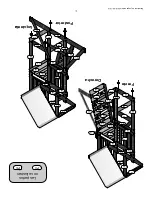
Page 50: ...10 09 1214 Frente Las partes no se ilustran P3 P6 K1 P2 Derecha Posterior Izquierda N3 N6 N4 P9s P8s N8 N9 N10 N10 N10 N10 N9 N5 N5 E2 E2 N7 K2 P5 P1 N1 N4 P10 K1 N2 N6 E1 E1 P1 N1 N5 N4 N4 P8s N8 K3 K3 K2 P5 P9s E2 N7 P1 P7 N5 P4 P2 ...

Page 51: ... 3 Ensamblaje de la estructura 10 Fase 4 Ensamblaje de la estructura 11 Fase 5 Ensamblaje del piso 12 Fase 6 Ensamblaje del refuerzo en ángulo 13 Fase 7 Ensamblaje de la pared 14 Fase 8 Ensamblaje del techo de dos aguas 15 Fase 9 Ensamblaje del techo de dos aguas 16 Fase 10 Ensamblaje de las agarraderas 17 Fase 11 Ensamblaje de la escalera 18 Fase 12 Ensamblaje de la escalera 19 Fase 13 Ensamblaje...

Page 52: ...el 24 Llaves de boca abierta Conductores Tuerca 7 16 9 16 Cinta de medir 3 8 Drive Ratchet 9 16 std sockets Martillo de orejas 9 16 tomas de profundidad 3 8 Cordless Drill o Taladro 1 8 5 16 Accesorios de perforación Electric 3 8 brocas Tornillos de cabeza Phillips 3 8 controlador de socket Tornillos de cabeza de par Un adulto w Phillips Straight Mazo de caucho Opcional ayudante de Adultos estorni...

Page 53: ... hardware adecuado en el lugar correcto al montaje de la unidad usted puede comparar el hardware a la página de la identificación de hardware NOTAS 1 No incluya la cabeza del perno en la medición de la longitud de un perno 2 Incluyen la longitud total del tornillo de la cubierta en la medición 60 70 3 80 90 120 110 130 140 150 100 20 3 4 1 1 2 10 1 4 5mm 4 5 2 50 40 30 19 5 5 92 9 4 2 85 Recomenda...

Page 54: ...rmación 8 Cuál es la mejor manera de comenzar a ensamblar la unidad de juegos Backyard Discovery recomienda retirar todas las piezas de las cajas y ordenarlas según el número de pieza antes de comenzar cualquier ensamblaje Esto no solo permitirá un ensamblaje más rápido sino que también permitirá identificar las piezas que puedan faltar o estar dañadas de modo que puedan ser reemplazadas antes del...

Page 55: ...bargo debido a que los niños pueden saltar deliberadamente de un columpio en movimiento el material de absorción de impactos debe extenderse al frente y parte posterior de un columpio a una distancia mínima de 2 veces el alto del punto pivotante medido desde un punto directamente debajo del pivote en la estructura de soporte X3 4 Esta información está destinada a ayudar a comparar las propiedades ...

Page 56: ...es y cadenas deberán retirarse y reemplazarse si se encuentra desgaste excesivo 6 Para las áreas oxidadas en elementos metálicos como las barras pasamanos los apoyos para las manos soportes etc Lije y repinte utilizando una pintura que no tenga base de plomo y cumpla con los requisitos del Título 16 CRF Parte 1303 7 Inspeccione las piezas de madera mensualmente Las fibras de la madera a veces se l...

Page 57: ...l manual de instrucciones La altura máxima de caída y el área de juegos recomendada también se encuentra a disposición en el manual de ensamblaje para la unidad específica 2 Se requiere supervisión en el sitio por parte de un adulto 3 Indique a los niños que no caminen cerca frente detrás o entre los columpios en movimiento u otras partes en movimiento de la unidad 4 Indique a sus niños que se sie...

Page 58: ...minuir la posibilidad de quemaduras graves Un tobogán que esté orientado hacia el norte recibirá menor cantidad de luz solar directa 9 Separe las actividades que impliquen movimientos activos de las pasivas Por ejemplo coloque las cajas de arena alejadas de los columpios o utilice una barandilla o barrera para separar la caja de arena del movimiento de los columpios Superficie sugerida para la zon...

Page 59: ...nule la garantía y o las violaciones a la seguridad podrían resultar en lesiones graves Este manual contiene información útil referente a la preparación para el ensamblaje el procedimiento de instalación y los requisitos de mantenimiento Recuerde siempre la seguridad de sus niños a medida que construye la estructura para juegos y cuando sus niños jueguen en ella Antes de que sus niños jueguen en l...

Page 60: ...Manual FAQ s Instrucciones de montaje Información sobre la garantía Play Deck De madera Playcenter 2010 Model 5010 Fabricante Backyard Discovery 3001 North Rouse Pittsburg KS 66762 Made in China Rev 01 28 2009 ...

Page 61: ... SWING BEAM ASSEMBLY INSTRUCTIONS A1 Attach the Swing Hangers to the Swing Beam using two 3 8 x 5 1 2 Hex Head Bolts 3 8 Lock Washers 3 8 Washers and 3 8 Spike Tee Nuts A1 Copyright Playground Inc If you need assistance with parts or have assembly questions please call Customer Service at 866 362 1123 Our regular office hours are Monday through Friday 7 00 a m to 4 00 p m Central Time LEISURE TIME...

Page 62: ... Lock Washer and 3 8 Flat Washer threading the bolt through the wooden parts into the Spike Tee Nut installed in Step 3 Tighten securely but don t over tighten Use any convenient long 3 8 bolt E1 Long Angle Brace 1 Hole 30 60 1 1 2 x 3 1 2 x 85 B1 Beam End Post 3 Holes 3 1 4 x 3 1 4 x 47 3 8 X 6 1 2 HEX HEAD BOLT 3 8 SPIKE TEE NUT 3 8 INTERNAL TOOTH LOCK WASHER SAE 3 8 FLAT WASHER STEP 3 STEP 4 E1...

Page 63: ...e and attach the E2 Beam End Support E2 to the assembly using two 3 Lag Screws Lock Washers and Washers in the center holes into B1 and two 2 1 2 Lag Screws Lock Washers and Washers into the E1 boards Tighten securely but do not over tighten G1 Beam Ground Board 4 Holes 1 x 5 1 2 x 89 5 16 X 2 LAG SCREW 5 16 INTERNAL TOOTH LOCK WASHER 5 16 FLAT WASHER E2 Beam End Support 4 Hole 1 1 2 x 3 1 2 x 40 ...

Page 64: ...and Lock Nut 5 16 X 2018 NYLOCK LOCK NUT 5 16 X 4 HEX HEAD BOLT 5 16 LOCK WASHER 5 16 FLAT WASHER Y1 Attach the Y16 Swing Assembly Mounts to the end of Swing Beam using two 4 Hex Bolts Lock Washers 4 Flat washers and secure with two 5 16 Nylock Nuts 5 16 X 2 HEX HEAD BOLT Y16 STEP 7 STEP 8 5 16 FLAT WASHER 5 16 INTERNAL TOOTH LOCK WASHER G4 M5 H6 C2 C2 ...

Page 65: ...ail Tighten securely but do not over tighten 5 16 x 2 HEX HEAD BOLT FLAT WASHER BOLT LOCK WASHER BOARD FLAT WASHER BARREL NUT 5 16 Metal stake installation measure in 8 from outside edge of G1 ground board for ground for stake location Now attach the stakes to G1 Ground Board using 1 Phillips Truss Head Bolt two Flat Washers Lock Washer and Barrel Nut Per Diagram at right You will need a long scre...

Page 66: ...LUMPIO INSTRUCCIONES DE ENSAMBLAJE A1 Fije los colgadores de los columpios a la barra para columpio A1 utilizando dos pernos cabeza hexagonal de 3 8 x 5 1 2 in 9 5 mm x 14 cm arandelas de seguridad de 3 8 in 9 5 mm arandelas de 3 8 in 9 5 mm y tuercas en T con espigas Copyright Playground Inc Si necesita ayuda con las partes o tiene preguntas sobre el ensamblaje por favor llame al Dpto de Servicio...

Page 67: ...avés de las partes de madera en la tuerca en T con espigas del paso 3 Apriete de forma segura pero no demasiado Utilice cualquier perno largo de 3 8 in 9 5 mm E1 Refuerzo largo en ángulo 1 agujero 30 60 1 1 2 x 3 1 2 x 85 B1 Poste para extremo de barra 3 agujeros 3 1 4 x 3 1 4 x 47 PERNO CABEZA HEXAGONAL DE 3 8 x 6 1 2 in 9 5 mm x 16 5 cm TUERCA EN T DE 3 8 in 9 5 mm CON ESPIGAS ARANDELA DE SEGURI...

Page 68: ...s tirafondo de 3 in 7 6 cm arandelas de seguridad y arandelas en los agujeros del centro en B1 y dos tornillos tirafondo de 2 1 2 in 6 3 cm arandelas de seguridad y arandelas en las tablas E1 Apriete de forma segura pero no demasiado G1 Tabla de apoyo A tierra 4 agujeros 1 x 5 1 2 x 89 ARANDELA DE SEGURIDAD DE 5 16 in 8 mm CON DIENTES INTERNOS ARANDELA PLANA DE 5 16 in 8 mm E2 Soporte de extremo p...

Page 69: ...Z A H E X AG O N A L D E 5 16 x 4 in 8 mm x 10 cm ARANDELA DE SEGURIDAD DE 5 16 in 8 mm ARANDELA PLANA DE 5 16 in 8 mm Y1 Fije los soportes para el ensamble de columpio Y16 al extremo de la barra para columpio utilizando dos pernos hexagonales de 4 in 10 cm arandelas de seguridad 4 arandelas planas y asegure con dos tuercas mecánicas de 5 16 in 8 mm PERNO CABEZA HEXAGONAL DE 2 in 5 cm Y16 PASO 7 P...

Page 70: ...Mida 8 in 20 3 cm hacia adentro desde el extremo exterior de la tabla a tierra G1 para la ubicación de la estaca Ahora fije las estacas a la tabla a tierra G1 utilizando el perno Phillips cabeza segmentada de 1 in 2 5 cm dos arandelas planas arandela de seguridad y arandela cilíndrica de acuerdo al diagrama de la derecha Necesitará un destornillador largo para apalancar En algunos casos es necesar...

Page 71: ...l G2 which will be a top rail on the back left of your sets Club House This space is the recommended location Using a 3 8 drill bit drill thru Sculptured Rail at marks per diagram Part 5047 Next Generation MONKEY BAR ASSEMBLY INSTRUCTIONS STEP 1 2 3 4 DOWN 6 22 STEP 2 N2 M6 M6 M8 E2 E3 Copyright Playground Inc If you need assistance with parts or have assembly questions please call Customer Servic...

Page 72: ...the holes in the other End Ladder Rail E1 and pound it down using the Spacer Block to prevent marking the Ladder Rail with the hammer STEP 3 Attach the Y40 Bracket to the ends of both Monkey Bar Rails using 2 Hex Head Bolts Lock Washers Washers and 5 16 Lock Nut Tighten securely but do not over tighten 5 16 X 2018 NYLOCK LOCK NUT Y40 Bracket E1 E1 22 Inside to Inside ...

Page 73: ... Flat Washers Tighten the screws securely but do not over tighten STEP 6 Attach the two Short Angle Braces E4 to the End Ladder Rails E1 with 3 1 4 Hex Bolts Lock Washers Flat Washers and Spike Tee Nuts Drill 3 16 pilot holes using the pre drilled holes in the Ground Board as guide and attach it to the Short Angle Braces using 2 Lag Screws Lock Washers and Flat Washers G1 E4 E4 E1 G1 ...

Page 74: ...s Flat Washers and Spike Tee Nuts and 1 1 2 Hex Head Bolts Lock Washers Flat Washers and Spike Tee Nuts STEP 8 5 16 x 3 HEX HEAD BOLT 5 16 x 1 HEX HEAD BOLT Swing up the End Ladder Assembly and line up the pre drilled holes in the Ladder Rails with the holes in the green Metal Triangles Secure with two 1 1 2 Hex Head Bolts Lock Washers Flat Washers and Spike Tee Nut Tighten securely but do not ove...

Page 75: ...HER BOARD FLAT WASHER BARREL NUT 5 16 Metal stake installation measure in 8 from outside edge of G1 ground board for ground stake location Then screw stake into ground using a long screw driver for leverage until stake is approximately 1 down from top of ground board Now using a 3 8 drill bit and hole in stake as guide drill thru ground board and attach using 1 Phillips Truss Head Bolt Flat Washer...

Page 76: ...zquierda de la casa club Este espacio es la ubicación que se recomienda Utilizando una broca para taladro de 3 8 in 9 5 mm taladre el larguero tallado en las marcas de acuerdo al diagrama Parte 5047 Última Generación PASAMANOS INSTRUCCIONES DE ENSAMBLAJE PASO 1 6 22 PASO 2 N2 M6 M6 M8 E2 E3 G2 de lado externo a lado externo Y14 La unidad puede que no luzca como esta ilustración 2 3 4 in 7 cm HACIA...

Page 77: ... que queden marcas en el larguero de la escalera producidas por el martillo PASO 3 Fije los soportes Y40 a los extremos de ambos largueros para el pasamanos utilizando pernos cabeza hexagonal de 2 in 5 1 cm arandelas de seguridad arandelas y la tuerca de seguridad de 5 16 in 8 mm Apriete de forma segura pero no demasiado Y40 Soporte E1 E1 22 in de borde interno a borde interno TUERCA MECÁNICA DE S...

Page 78: ...gas Taladre agujeros piloto de 3 16 in 4 8 mm utilizando los agujeros pre taladrados en la tabla de tierra como guía y fíjela a los soportes cortos en ángulo utilizando tornillos tirafondo de 2 in 5 1 cm arandelas de seguridad y arandelas planas G1 E4 E4 E1 G1 Apriete los tornillos de forma segura pero no demasiado ARANDELA DE SEGURIDAD DE 5 16 in 8 mm ARANDELA PLANA DE 5 16 in 8 mm TORNILLO TIRAF...

Page 79: ... planas y tuercas en T con espigas PASO 8 Gire el ensamble de escalera terminal y alinéelo con los agujeros pre taladrados en los largueros de la escalera con los agujeros en los triángulos verdes metálicos Asegure con dos pernos cabeza hexagonal de 1 1 2 in 3 8 cm arandelas de seguridad arandelas planas y tuerca en T con espigas Apriete de forma segura pero no demasiado ARANDELA DE SEGURIDAD DE 5...

Page 80: ...destornillador largo para apalancar hasta que la estaca esté aproximadamente 1 in 2 5 cm hacia abajo con respecto a la parte superior de la tabla a tierra Ahora utilizando una broca de taladro de 3 8 in 9 5 mm y el agujero en la estaca como guía taladre a través de la tabla a tierra y fije utilizando un perno Phillips cabeza segmentada de 1 in 2 5 cm arandelas planas y arandelas de seguridad con t...

Reviews: