background image

Page 52

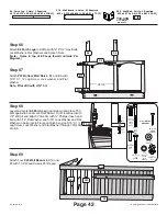
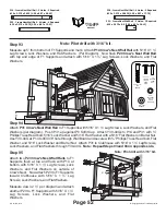
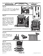
Step 93

Step 94

Step 95

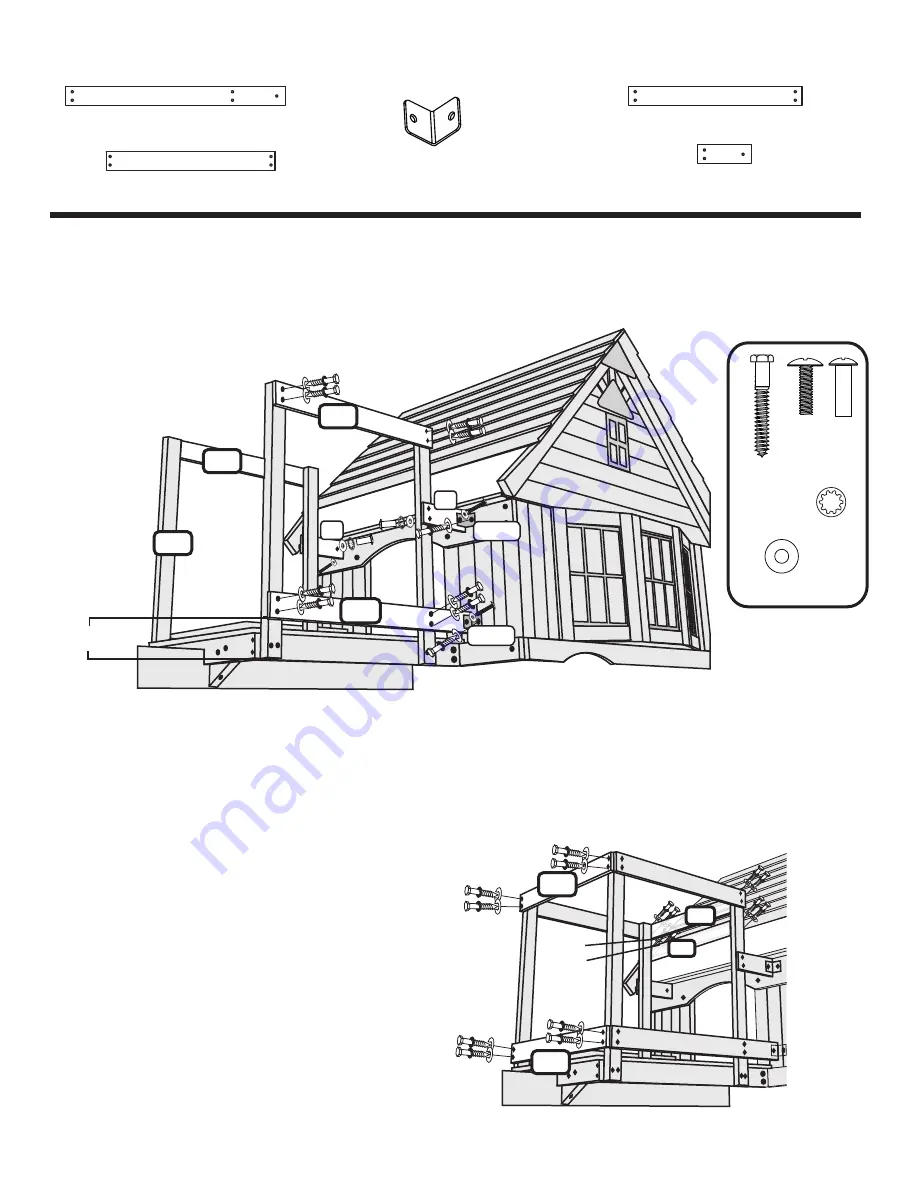
Measure up 5” from bottom of F1 Supports and mark.  Attach 

P14 Crow's Nest Wall Rail

 with 5/16” X 1 ½” 

Lag Screws, Lock Washers, and Flat Washers.  (Per Diagram).  Now flush 

P20 Crow's Nest Wall Rail


with top and edge of F1 Supports and attach with 5/16” X 1 ½” Lag Screws, Lock Washers, and Flat 
Washers.

Attach 

P31 Crow's Nest Wall Rail

 to F1 Supports with 5/16” X 1 ½” Lag Screws, Lock Washers, and Flat 

Washers (per diagram).  Push P31 up against P8 Soffit Cap.  Attach Y30-40Gs to P14 and P31 with ¾” 
Phillips Truss Head bolt, 5/16” Lock Washer and 5/16” Flat Washer with a 5/16” Flat Washer on Barrel Nut.  
Use Y30-40G at P14 to drill 3/8” hole through Wall Board and secure with ¾” Phillips Truss Head bolt, Flat 
Washer, and 5/16” Lock Washer and Barrel Nut.  Attach P31 to Clubhouse with 5/16” X 1 ½” Lag Screws, 
Lock Washers, and Flat Washers through Y30-40G.  

Note:  Repeat Steps 93 and 94 on opposite side.

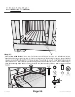
Attach two 

P23 Crow's Nest Wall Rails

 to F1 

Supports  flush  at  top  and  flush  with  P14  at 
bottom with 5/16” X 1 ½” Lag Screws, Lock 
Washers,  and  Flat  Washers  on  outside  of 
Crow's Nest.  Now attach P23 to F1 Supports 
toward  Clubhouse  with  5/16”  X  1  ½”  Lag 
Screws, Lock Washers, and Flat Washers.  

Measure down 2 ½” per diagram and attach 
another P23 to F1 Supports with 5/16” X 1 ½” 
Lag  Screws,  Lock  Washers,  and  Flat 
Washers.

P14

F1

P20

P20

P31

P31

Y30-40G

Y30-40G

P23

P23

P23

P23

P14 - Crows Nest Wall Rail - 5 Holes - 2 Required
.625 x 3.375 x 38.75 [1.59 x 8.57 x 98.43]

P20 - Crows Nest Wall Rail - 4 Holes - 2 Required
.625 x 3.375 x 30.625 [1.59 x 8.57 x 77.79]

P23 - Crows Nest Wall Rail - 4 Holes - 4 Required
.625 x 3.375 x 29.75 [1.59 x 8.57 x 75.57]

P31 - Crows Nest Wall Rail - 3 Holes - 2 Required
.625 x 3.375 x 9.5 [1.59 x 8.57 x 24.13]

5”

2 1/2”

5/16 X 1 1/2"

LAG

SCREW

1/4 X 3/4"
PHILLIPS

TRUSS

HEAD

BOLT

1/4"

BARREL

HEAD

NUT

5/16"

INTERNAL

TOOTH

LOCK

WASHER

5/16" FLAT
WASHER

© Copyright Leisure Time Products Inc.

Sky Fort 09-0112

Y30-40G

2" x2" METAL

BRACKET

Note: Pilot drill with 3/16” bit.

Note: Pilot drill with 3/16” bit.

Summary of Contents for Sky Fort 6009

Page 1: ...ons can you be assured of safe play time on any product designed for children If you need assistance with parts or have assembly questions please call Customer Service at 800 765 4138 Please read the...

Page 2: ...installed on has one or two climbing towers the metal level ground Installation on sloping plates must be installed so that each ground will cause your set to lean and in climbing tower is perpendicul...

Page 3: ...slick surface could cause a fall and they should never slide down head first Children should NOT twist swing chains or loop them over the top support beam because this will weaken and reduce the stre...

Page 4: ...poor weather conditions Wear proper clothing and safety equipment safety glasses boots and gloves while assembling your gym set Tools and Materials Required Claw Type Hammer 10 ft Tape Measure Framin...

Page 5: ...ment of the swings Set needs to be installed on solid ground for anchoring purposes Do not install your gym set over concrete gravel asphalt packed earth or any other hard surface A FALL ON TO A HARD...

Page 6: ...SAFE PLAY AREA DIAGRAMS Page 5 SAFETY ASSEMBLY Landscape Timbers 6 from play structure Safe play area using recommended ground cover 28 8 Copyright Leisure Time Products Inc Sky Fort 09 0112...

Page 7: ...Lag Screw Typical Installation Wood Screw Use a screw driver or an electric drill or screw gun to drive screws Lubricate the threads of the screws with beeswax or soap to ease installation and minimi...

Page 8: ...FO R C H I L D B1 E1 E3 E6 K 1 6 L K16R H2 H5 H6 H10 P1 P4 P7 P10 P11 P13 P14 P16 P17 P19 P20 P22 P31 P32 P33 Q11 Q 14 SA1 SA2 SA3 E1 K8 K8 B1 O1 O2 O3 O3 O3 O3 O3 O3 O1 O1 O2 O2 SA1 E 8 E 8 Q 1 4 Q 1...

Page 9: ...E11 E11 B3 B3 E4L E4R E7 Q7 P24 B5 P9 P24 K7 K1 K2 P4 P7 P27 Q12 Q8 Q12 P28 P30 E 8 E 8 SA1 SA3 Q8 Q12 Q12 B1 E3 E1 H2 E1 K8 K8 K 14 P12 P12 P15 B3 K4 K4 E12R E12L H4 H6 K18 O5 K10 K3 K13 Q6 Q14 Q11...

Page 10: ...nt 4 Holes 1 Required 3 x 3 x 50 375 7 62 x 7 62 x 127 95 B7 Club House Corner Back Right 4 Holes 1 Required 3 x 3 x 54 7 62 x 7 62 x 137 16 E1 End Ladder Rail 8 Holes 2 Required 1 375 x 3 375 x 90 5...

Page 11: ...3 Holes 2 Required 1 375 x 3 375 x 10 5 3 49 x 8 57 x 26 67 F1 Crows Nest Wall Support 2 Holes 4 Required 1 375 x 2 375 x 37 5 3 49 x 6 03 x 95 25 H1 Swing Beam Ground Board 4 Holes 1 Required 9375 x...

Page 12: ...60 2 38 x 8 57 x 152 40 K8 Monkey Bar Angle Brace 1 Holes 2 Required 9375 x 3 375 x 57 5 2 38 x 8 57 x 146 05 K9 Club House Wall Rail 4 Holes 1 Required 9375 x 3 375 x 50 375 2 38 x 8 57 x 127 95 K10...

Page 13: ...Required 625 x 3 375 x 81 875 1 59 x 8 57 x 207 96 P2 Top Wall Rail 5 Holes 1 Required 625 x 3 375 x 80 1 59 x 8 57 x 203 20 P3 Bottom Wall Rail 3 Holes 2 Required 625 x 3 375 x 80 1 59 x 8 57 x 203 2...

Page 14: ...Required 625 x 3 375 x 30 625 1 59 x 8 57 x 77 79 P21 Club House Wall Board 6 Holes 5 Required 625 x 3 375 x 29 875 1 59 x 8 57 x 75 88 P22 Club House Wall Rail 2 Holes 3 Required 625 x 3 375 x 30 1 5...

Page 15: ...Page 14 WOODEN PARTS P31 to Q15 Copyright Leisure Time Products Inc Sky Fort 09 0112...

Page 16: ...eam Support 3 Hole 1 Required 3 375 x 3 375 x 47 8 57 x 8 57 x 119 38 SC1 Top Floor Board 9 Holes 1 Required 625 x 4 x 77 9375 1 59 x 10 16 x 197 96 SC2 Top Floor Board 5 Holes 1 Required 625 x 4 x 39...

Page 17: ...OM BOTTOM OF HEAD TO BOTTOM OF BOLT 5 16 X 2 HEX HEAD BOLT ZHB2 3 8 X 6 1 2 HEX HEAD BOLT ZHB6 6 5 5 16 X 2 3 4 HEX HEAD BOLT ZHB2 3 4 3 8 X 6 HEX HEAD BOLT ZHB6 6 5 16 X 3 1 4 HEX HEAD BOLT ZHB3 1 4...

Page 18: ...ZPBN3 4 3 8 SPIKE TEE NUT ZTN3 8 5 16 SPIKE TEE NUT ZTN 3 8 INTERNAL TOOTH LOCK WASHER ZLW3 8 5 16 INTERNAL TOOTH LOCK WASHER ZLW5 16 SAE 3 8 FLAT WASHER ZFW3 8 5 16 FLAT WASHER ZFW5 16 8 X 3 4 WASHE...

Page 19: ...Barrel Nut 1 4 20 x 3 4 long 50 ZLS2 1 2 Lag Screw 5 16 x 2 1 2 42 ZLS2 Lag Screw 5 16 x 2 53 ZLS1 1 2 Lag Screw 5 16 x 1 1 2 100 ZJC1 1 2 Joint Connector Screw 5 16 x 1 1 2 w 11 16 Head Diameter 5mm...

Page 20: ...IN N TE E ND DR ED F CHIL OR METAL ID PLAQUE Z3 QUICK LINK SWING HANGER LARGE WINDOW FRAME 6 REQUIRED 2 GLIDER ARMS W CHAIN 1 GLIDER SEAT MEDIUM WINDOW FRAME 2 REQUIRED SMALL TRIANGLE BRACE 5 REQUIRED...

Page 21: ...uare B2 Middle Post Lay B1 and two B3 Tower Legs on ground Attach H3 Top Floor Rail with 5 16 X 3 Hex Bolts Lock washers Flat Washers and SpikeT Nuts Using holes in H4 as guide pilot drill tower legs...

Page 22: ...tom Floor Rail to inside of B3 legs with 5 16 X 2 lag screws Lock Washers Flat Washers and H6 Bottom Floor Rail to B3 and B2 legs with 5 16 X 2 lag screws Lock Washers and flat washers Note remember t...

Page 23: ...1 below top of floor rails and finish attaching E11 with 5 16 X 2 Lag Screws Lock Washers and Flat Washers through H10 s and H11 floor rails into deck braces Note remember to use 3 16 bit to pilot dr...

Page 24: ...ired 625 x 4 x 39 5 1 59 x 10 16 x 100 33 SC3 Top Floor Board 4 Holes 1 Required 625 x 4 x 35 5 1 59 x 10 16 x 90 17 SC4 Bottom Floor Board 4 Holes 2 Required 625 x 4 x 35 5 1 59 x 10 16 x 90 17 8 X 1...

Page 25: ...up from Floor Rail Note pilot drill with 3 16 bit Measure up 11 from top of floor boards and mark center of B3 legs Level K12L and K12R and attach to B3 Legs with 5 16 X 2 Lag Screws Lock Washers and...

Page 26: ...with 5 16 X 2 Lag Screws Lock Washers and Flat Washers Flush with top of P3 and Level across B3 legs Note pilot drill with 3 16 bit K14 K10 K10 K3 K3 Note Picnic Seats are removed from this drawing to...

Page 27: ...er of table with 1 1 8 Wood Screws Per diagram K18 K3 P15 P12 E12R Right Picnic Table Brace 2 Holes 1 Required 1 375 x 3 375 x 17 5 3 49 x 8 57 x 44 45 E12L Left Picnic Table Brace 2 Holes 1 Required...

Page 28: ...K12L STEP 25 Attach K6 Front Wall Rail to B1 Tower Legs using 5 16 X 3 Hex Bolts Lock Washers Flat Washers and SpikeT Nuts in upper holes Use 5 16 X 2 Lag Screws Lock Washers and Flat Washers in botto...

Page 29: ...ill Floor with 3 8 drill bit and secure Y30 40G to floor with 3 4 Phillips Truss Head Bolt and 5 16 Washer and 5 16 Lock Washer and Barrel Nut Pilot drill with 3 16 bit Finish securing Y30 40G to B5 w...

Page 30: ...19 Wall rail to B1 Leg and B7 Corner Post with 5 16 x 3 Hex bolt Lock Washer Flat Washer and Spike T Nut per diagram B7 B1 K19 Step 31 Attach B6 Clubhouse Corner front right to K19 Wall Rail with 5 16...

Page 31: ...Post with 3 16 bit and attach Step 34 Attach K2 Roof Support Rails to B5 and B7 and to B4 and B6 with 5 16 X 3 Hex Bolt Lock Washer Flat Washer and SpikeT Nuts K2 K2 B6 B1 B1 B6 B2 B4 K2 Roof Support...

Page 32: ...to B5 Post Note Hole in P22 at 1 from edge towards Floor P22 K2 K2 B4 B5 B4 B1 B1 B6 B5 K5 Front Club House Wall Rail 4 Holes 1 Required 9375 x 3 375 x 60 2 38 x 8 57 x 152 40 P9 Club House Wall Rail...

Page 33: ...nd B4 flush with K2 roof support Rails with 5 16 X 2 Lag Screws Lock Washers and Flat Washers K9 B4 B5 K13 Club House Wall Rail 3 Holes 1 Required 9375 x 3 375 x 28 625 2 38 x 8 57 x 72 71 K9 Club Hou...

Page 34: ...rel Nut E7 K5 E7 B1 B1 B4 B6 Step 43 Now finish attaching E7 to Y30 40G L Bracket with 5 16 x 1 Lag Screw Lock Washer and Flat Washer H8 House Wall Rail 6 Holes 1 Required 9375 x 5 375 x 50 375 2 38 x...

Page 35: ...ubhouse Wall Board to K2 K7 against B7 Post with 1 1 8 Wood Screws Attach six P24 Wall Boards to K7 and P22 with 1 1 8 Wood Screws B7 P25 P22 P24 K13 P25 P6 Club House Wall Board 6 Holes 1 Required 62...

Page 36: ...ards flush with top of P10 s to K5 Rail with 1 1 8 Wood Screws K1 P24 P9 P10 P10 P17 P32 B6 E7 K5 P24 Wall Board 4 Holes 23 Required 625 x 3 375 x 28 625 1 59 x 8 57 x 72 71 P17 Wall Board Front Windo...

Page 37: ...with 1 1 8 Wood Screws Note These holes will be used in later step Q2 P10 SD1 B6 H8 B2 E5 E5 Q2 P10 B7 K19 P2 B8 Q2 Club House Wall Board 3 Hole 2 Required 625 x 2 375 x 50 5 1 59 x 6 03 x 128 27 Q4...

Page 38: ...Screws to prevent them from pushing through per diagram Repeat procedure on left side Bay Window Per diagram Note H9 is 2 3 4 from posts H9 H9 Q8 Q12 Q8 Q12 Q12 Q8 H9 Window Board 5 Holes 4 Required 9...

Page 39: ...Clubhouse Rafter flush at top and with 2 overhang in front with 1 Wood Screws Now on right side flush a SA1 with the top of SA1 You attached on left side with 2 overhang in front with 1 Wood Screws Th...

Page 40: ...375 x 46 75 1 59 x 8 57 x 118 75 P13 Gable Board 2 Holes 1 Required 625 x 3 375 x 39 75 1 59 x 8 57 x 100 97 P18 Gable Board 2 Holes 1 Required 625 x 3 375 x 32 75 1 59 x 8 57 x 83 19 P27 Gable Windo...

Page 41: ...on top of K9 Rail with 1 Wood Screws Note Flush with inside of K9 Rail Attach P8 Soffit Cap on top of H8 Rail with 1 Wood Screws flush with inside of H8 P7 P4 P11 P13 P18 Q6 E8 E8 Q14 Q11 P7 P4 P27 P...

Page 42: ...1 8 Wood Screws Note Put screws towards bottom of SA1 to prevent screw from boring through On left side push Q3 support and secure same way per diagram Attach Y30 40G to Q3 s at Peak with Washer Head...

Page 43: ...ing 5 16 X 1 Lag Screw Lock Washer and Flat Washer through Y30 40G into E6 Attach Four P24 Wall Boards to K19 and P2 with 1 1 8 Wood Screws 2 5 8 apart P24 P24 K19 P2 P24 Wall Board 4 Holes 23 Require...

Page 44: ...el Roof and fasten Back Rafter Assembly to K5 Rail on right side with 5 16 X 1 Lag Screw Lock Washer and Flat Washer per diagram P19 K16L Porch Roof Rafter 1 Holes 2 Required 9375 x 3 375 x 24 5 2 38...

Page 45: ...ble 2 Holes 1 Required 625 x 2 375 x 15 1 59 x 6 03 x 38 10 Q7 Entry Ladder Back 2 Holes 2 Required 625 x 2 375 x 21 75 1 59 x 6 03 x 55 25 Q13 Front Porch Gable 2 Holes 2 Required 625 x 2 375 x 9 5 1...

Page 46: ...nd drill 3 8 hole Attach to Floor Rail with 5 16 X 2 Lag Screws Lock Washers and Flat Washers K4 Rock Wall Rail No Holes 2 Required 9375 x 3 375 x 63 2 38 x 8 57 x 160 02 O1 Rock Wall Slat 8 Holes 4 R...

Page 47: ...H2 Ground Board into K8 Angle Braces with 5 16 x 1 1 2 Lag Screws Lock Washers and Flat Washers Attach P35 End Ladder Back to E1 End Ladder Rail with 2 Wood Screws K8 H2 K8 E1 E1 End Ladder Rail 8 Ho...

Page 48: ...h to Y1 Triangles with 5 16 X 1 Hex Bolts Lock Washers Flat Washers and SpikeT Nuts 1 E3 Monkey Bar Rail 8 Holes 2 Required 1 375 x 3 375 x 71 3 49 x 8 57 x 180 34 LARGE METAL TRIANGLE Y35 22G Monkey...

Page 49: ...rd 4 Holes 1 Required 9375 x 5 375 x 87 2 38 x 13 65 x 220 98 SB1 Swing Beam Support 3 Hole 1 Required 3 375 x 3 375 x 47 8 57 x 8 57 x 119 38 5 16 X 1 1 4 HEX HEAD BOLT 5 16 X 4 HEX HEAD BOLT 5 16 X...

Page 50: ...5 16 X 5 3 4 HEX HEAD BOLT 3 8 SPIKE TEE NUT 3 8 INTERNAL TOOTH LOCK WASHER 3 8 FLAT WASHER Copyright Leisure Time Products Inc Sky Fort 09 0112 Using holes in K19 Rail as guide drill thru E5 with 3...

Page 51: ...Lock Washers Flat Washers and SpikeT Nuts inserted per diagram Note Just snug Level Crow s Nest Floor Rails and attach E14 s to A1 Beam with 5 16 X 2 Lag Screws Lock Washers and Flat Washers Now fini...

Page 52: ...quired 1 375 x 3 375 x 24 25 3 49 x 8 57 x 61 60 F1 Crows Nest Wall Support 2 Holes 4 Required 1 375 x 2 375 x 37 5 3 49 x 6 03 x 95 25 O4 Crows Nest Floor Board 4 Holes 9 Required 625 x 4 375 x 27 1...

Page 53: ...osite side Attach two P23 Crow s Nest Wall Rails to F1 Supports flush at top and flush with P14 at bottom with 5 16 X 1 Lag Screws Lock Washers and Flat Washers on outside of Crow s Nest Now attach P2...

Page 54: ...Lock Washers and Flat Washers into 5 16 Spike T Nuts placed in E5 Rail in earlier step R2 R1 R1 R1 Crows Nest Wall Board 2 Holes 18 Required 625 x 1 375 x 30 1 59 x 3 49 x 76 20 R2 Crows Nest Wall Bo...

Page 55: ...in Y10 16 5G Metal Grip pilot drill and finish securing with lags and washers Back Wall Opening Entry Ladder attach Y10 16 5G Metal Grips to B7 Post measure up 4 and pilot drill post with 3 16 drill b...

Page 56: ...w Crows Nest to swing hangers Tighten the quick link with a wrench The quick link must be tightened so that it cannot be opened by hand Slip the Plastic Safety Tubes on the Carabiner Copyright Leisure...

Page 57: ...attach to floor with 1 1 8 wood screws Place Slide on top of R3 and using holes as guide mark floor boards Remove Slide and drill through floor boards with 3 8 drill bit Attach Slide using 1 Step bol...

Page 58: ...l hardware store Swing hangers check to insure correct installation Make sure that the bend of the swing hanger is positioned tightly against the stop washer and the ladder or swing beam The axis of t...

Page 59: ...thering process of all wood exposed to the elements Checks occur after the wood has been wet and outside surfaces dry faster than inside surfaces Checks mainly affect the aesthetics of your play produ...

Page 60: ...the bolts Question Why does my play product have mold growing on it What can I do to remove it and keep it clean of mold and mildew Answer Because the structure is wooden rather than concrete or steel...

Page 61: ...r in all INC Ready to Assemble sets is covered by a 5 year pro rated warranty againstwoodrotandtermitedamage Non wooden parts such as hardware roped or chained accessories slides metal or plastic comp...

Page 62: ...b Floor Add on Kit Sand Box Cover Infant Swing These accessories are Available a samsclub com t Steering Wheel Replacement Parts Other Accessory Items Yellow Plastic Hand Grips Belt Swing Trapeze Bar...

Reviews: