5
ASSEMBLY INSTRUCTION
STEP 1
Remove all the components from the carton.
STEP 2
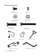
Lift the left upright (4) and right upright (3). Tightly fasten using two 5/16” x 3” button head bolt (83) and two
5/16”x18x1.5t flat washers (69). Tighten the 3/8” x 2” thumb head bolt (54) and the 3/8”x7t nylon nut (65) that
is
pre-assembled on the base frame (2).
STEP 3
Secure the console
support (5) to the left and right uprights (4 / 3)
using
one
3/8” x 46m/m button head bolt (55)
and one 3/8” x 19 x1.5t flat washer
(71)
and one lock nut (65).
Secure the front of the uprights (4 / 3) using one
5/16” x 1/2:” button head bolt (84) and one 5/16” x 18 x 1.5T flat washer (69). Tighten the 3/8” x 1-3/4” button
head bolt (55) and 3/8” x 19 x1.5t flat washer
(71)
that is pre-assembled on the uprights.
STEP 4
Connect the handpulse wire (93) to the back of the console (14).
Connect the computer wire (38) to the back of the console (14).
Attach the console (14) to the console support (5) using four M5x15mm button head bolts (60) found on the
back of the console.
ENSURE THAT ALL NUTS AND BOLTS ARE FIRMLY TIGHTEN
Summary of Contents for 1610636-1
Page 7: ...6 ASSEMBLY DIAGRAM...
Page 26: ...25...


