6800/7000 Series - Audio and Video Multi/Demultiplexing Products Installation and Operation Manual
81
Signal Flow
Chapter 7: DEC-6804 Decoder and DES-6804 Decoder with Frame Synchronizer
Signal Flow
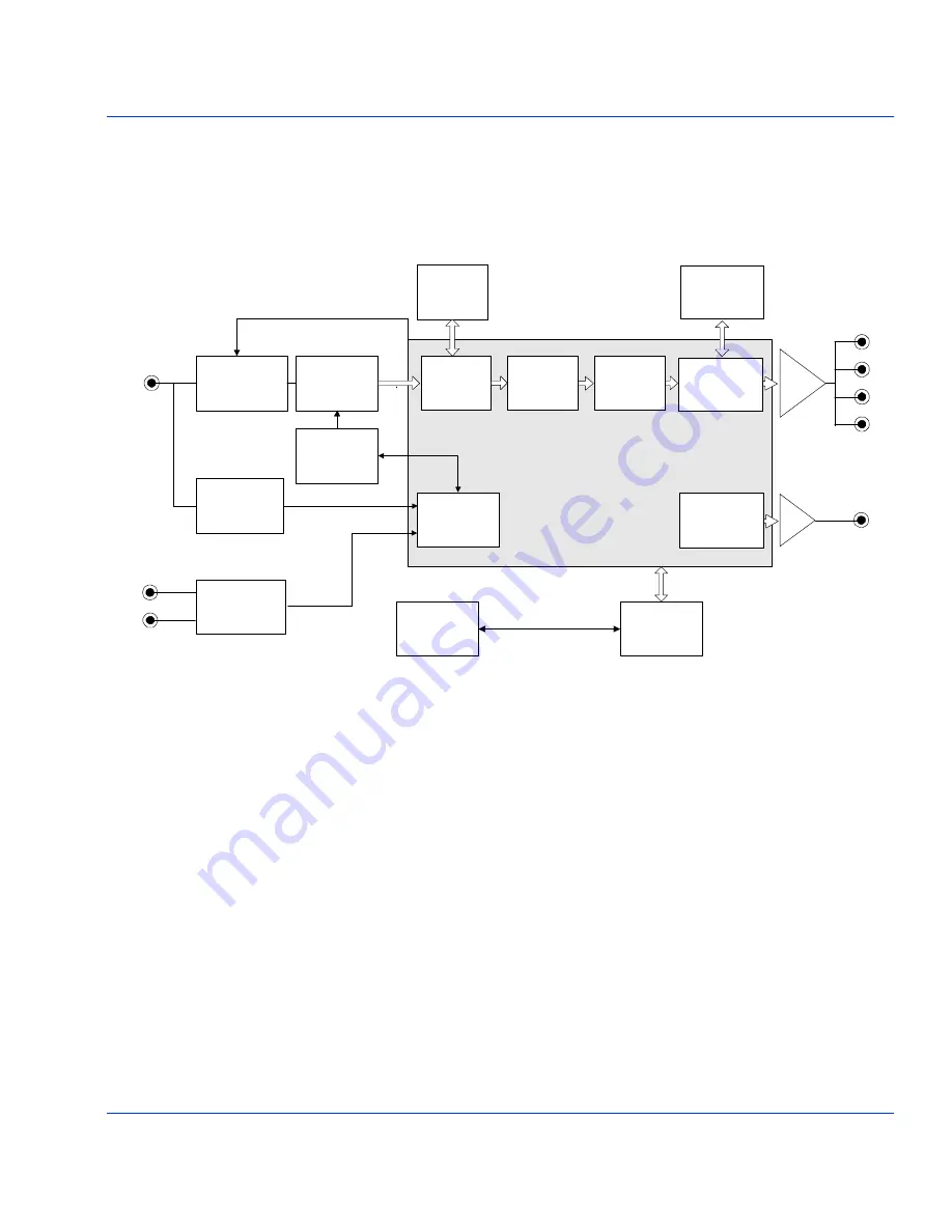
Figure 7-1 is a functional block diagram that describes the signal flow of
the DEC-6804 and DES-6804 modules.
Figure 7-1.
Functional Block Diagram of the DEC/DES-6804 Modules
FPGA Video Processing Unit
12-Bit A/D
Converter
Video
Preprocessing
Sync
Separator
Line
Memory
Clock
Generator
and PLL
CPU
Control
Unit
User
Interface
Clock
and PLL
Control
SDI
Output
Clamp Control
Serializer
2-D Comb
Filter
Color
Demodulator
Data
Formatter
Reference
Composite
Video
I/O
Delay
SDI
Output
Serializer
Primary
Composite
Video
2
I C Bus
Genlock
(DES-6804 Only)
Audio Sync
Interface
(DES-6804 Only)
Frame
Synchronizer
(DES-6804 Only)
Frame
Memory
(DES-6804 Only)

