6800/7000 Series - Audio and Video Multi/Demultiplexing Products Installation and Operation Manual
137
Jumper Settings
Chapter 9: MXA-6800-AES and MXA-6801-A2/A4 Video/Audio Multiplexer Module
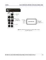
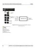
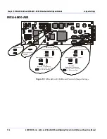
MXA-6800-A2/A4
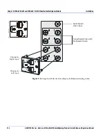
Figure 9-10.
MXA-6801-A2/A4 Full Board with Jumper Settings
Operation
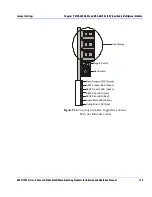
The seven segment LED display and discrete LEDs (on the front edge of
the board) show the current status of the MXA-6801-A2/A4. The LED
readout displays abbreviated names for the functions/parameters
selected by the Rotary Switch (
SW1
).
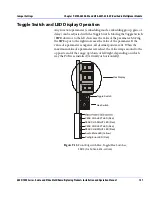
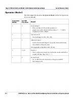
The MXA-6801-A2/A4 has three operating modes (OS1, OS2, OS3) and
the
SW1
is used to select specific functions/parameters within them. For
more detailed information on functions/parameters, the
SW1
and the
use of the Toggle Switch (
SW2)
.
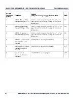
See
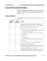
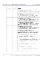
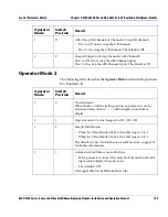
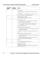
“Control Parameters Summary” on page 142 and “Control
Parameter Details” on page 147 for more information.
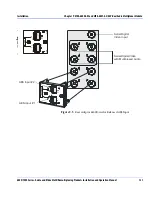
Should always
be
during normal
operation.
OFF
J4
OFF
J2
J2
Remote
Local
Local/Remote Control
Analog Audio
Input Termination
Channel B Right
Channel A Right
Channel B Left
Channel A Left
Open (default)
Open (default)
Open (default)
Open (default)
600
Ω
600
Ω
600
Ω
600
Ω
Common-Mode Rejection
Adjustment Potentiometers:
these are factory set and sealed.
Warning!
DO NOT ADJUST
THESE POTS


