Chapter 11: VTS-6801 Video Timing Switcher
Control Function Details
180
6800/7000 Series - Audio and Video Multi/Demultiplexing Products Installation and Operation Manual
Control Function Details
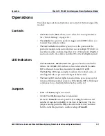
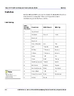
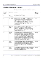
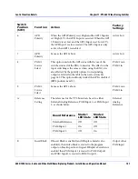
The following table describes the control function in detail:
Switch
Position
(SW1)
Function
Action
Factory
Settings
0
No
adjustment
No parameters can be adjusted.
1
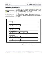
Lock mode
Lock
mode can be set to
525
,
625
, or
Auto Detect
. In
Auto
mode the system detects the standard of the chosen
reference and automatically sets the system standard.
Setting the
Lock
mode to
525
or
625
forces the system to
the selected standard. If any input conflicts with the set
standard, an error light will be illuminated for that
particular input.
Auto
2
Horizontal
Delay
This allows for horizontal timing adjustments or delays
between the serial input video and the output. The
adjustment is made in (37 ns) increments or decrements.
Since both serial inputs are locked together horizontally,
this affects both video streams.
0 sec
3
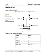
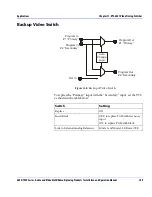
Replace
Serial
When enabled the other SDI program is routed to the
program output when the currently selected SDI program
input signal is not lockable. If Insert Black is also enabled
on breakup or loss of signal, Video Black is routed to the
program output. If Replace Serial is disabled, PGM Input
1 is routed to PGM Output 1 and PGM Input 2 is routed
to PGM Output 2 regardless of the state of the input signal
(and regardless of the setting of Insert Black).
Disabled
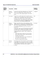
4
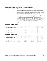
GPI 1
Enable
When GPI 1 is enabled (and the GPI 1 input is asserted).
the PGM Input 2 is switched to PGM Output 1. If the GPI
1 input is de-asserted, then PGM Input 1 is routed to
PGM Output 1. If GPI 1 is disabled, then GPI 1 Input is
ignored.
Disabled
5
GPI 2
Enable
If GPI Input 2 is asserted, then PGM Input 1 is switched to
PGM Output 2. If GPI Input 2 is de-asserted, then PGM
Input 2 is routed to PGM Output 2.
Disabled


