6800/7000 Series - Audio and Video Multi/Demultiplexing Products Installation and Operation Manual
181
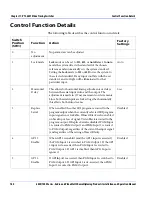
Control Function Details
Chapter 11: VTS-6801 Video Timing Switcher
6
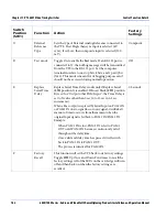
GPI 1
Polarity
When the GPI 1 Polarity is set High and the GPI 1 Input is
set High (5 V), the GPI 1 Input is asserted. When the GPI
1 Polarity is set Low and the GPI 1 Input is set Low (0 V),
the GPI Input 1 is also asserted. The GPI 1 Input is only
active when GPI 1 is enabled.
Active Low
7
GPI 2
Polarity
Same as for GPI 2 above.
Active Low
8
PGM 1
Source
Select
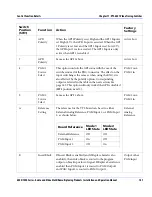
This option controls the GPI status with the use of the
switches instead of the BNC connector. The effect on the
input switching is the same as when using the BNC, it is
also affected by the polarity option. Corresponding
outputs are listed in the table in the next section;
See
page 183. This option will only work if the GPI is disabled
(
SW1
position 4 and 5).
PGM 1 out--
PGM 1 in
9
PGM 2
Source
Select
Same as for GPI 2 above.
PGM 2 out--
PGM 2 in
A
Reference
Setting
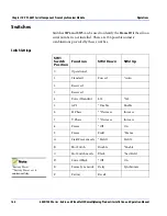
The reference for the VTS board can be set to either
External Analog Reference, PGM Input 1, or PGM Input
2, as shown below:
External
Analog
Reference
B
Insert Black
If Insert Black is enabled (and if Replace Serial is also
enabled), then video black is routed to the program
output on breakup or loss of signal. If Replace Serial is not
enabled then PGM Input 1 is routed to PGM Output 1
and PGM Input 2 is routed to PGM Output 2.
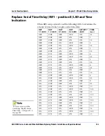
Output other
PGM input
Switch
Position
(SW1)
Function
Action
Factory
Settings
Board Reference
Mode 1
LED State
Mode 2
LED State
External Reference
Off
Off
PGM Input 1
On
Off
PGM Input 2
Off
On

