6800/7000 Series - Audio and Video Multi/Demultiplexing Products Installation and Operation Manual
185
Input Switching with GPI Controls
Chapter 11: VTS-6801 Video Timing Switcher
Input Switching with GPI Controls
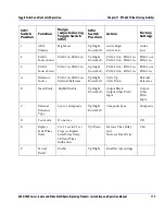
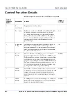
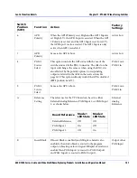
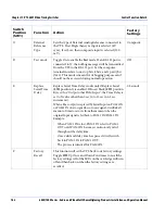
Input switching between the two sets of outputs is controlled through
the use of GPI inputs 1 and 2. Each GPI control determines the switching
of one video input. The effect of a high or a low from each GPI control is
also affected by the polarity option of
SW1
, positions 6 and 7.
The following tables describe the actions and effects when the polarity is
active high, the opposite of this is true for a polarity of active low. If the
GPI signal is low, then the input is passed straight through to its
appropriate output. In contrast to this, if the GPI signal is high, then the
input is switched to the opposite output. Shown below are the possible
combinations of GPI controls and the input which appears at each
output.
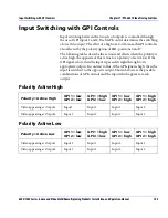
Polarity Active High
Polarity Active Low
Polarity = Active High
GPI 1 = low
GPI 2 = low
GPI 1 = high
GPI 2 = low
GPI 1 = low
GPI 2 = high
GPI 1 = high
GPI 2 = high
Video appearing at Output 1
Input1
Input 2
Input 1
Input 2
Video appearing at Output 2
Input 2
Input 2
Input 1
Input 1
Polarity = Active Low
GPI 1 = low
GPI 2 = low
GPI 1 = high
GPI 2 = low
GPI 1 = low
GPI 2 = high
GPI 1 = high
GPI 2 = high
Video appearing at Output 1
Input 2
Input 1
Input 2
Input 1
Video appearing at Output 2
Input 1
Input 1
Input 2
Input 2

