6800/7000 Series - Audio and Video Multi/Demultiplexing Products Installation and Operation Manual
5
Installation
Chapter 1: ADC-6801 CAV to SDI Converter Module
Installation
This module must be installed into an FR-6804 or FR-6804-1 mounting
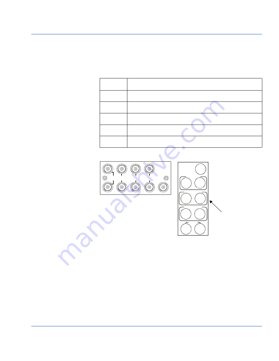
frame to meet CE requirements. The back module layout is shown below
and is connected as follows:
Figure 1-1.
ADC-6801 Back Module and Overlay
The inputs on the back module are looping. If the loop is not required,
external terminations must be connected to the spare BNCs.
The external sync input can be terminated on-board by installing
jumper
J8
or can be externally looped.
See
Figure 1-2, on page 7 and
see
also “Setup and Control”, on page 8
for further information.
Signal
Descriptions
Sync In
External color black or TTL level sync (optional)
G/Y
Green or Y signal (looped)
B/B-Y
Blue or B-Y signal (looped)
R/R-Y
Red or R-Y signal (looped)
Serial Out
SMPTE 259-C serial outputs
ADC-6801-M
SERIAL
OUT
R/R-Y
LOOP
B/B-Y
LOOP
G/Y
LOOP
SYNC
IN
This back module is used when the
ADC-6801 module is installed into
either a FR-7001 series or FR-7000MB
MIX BOX frame.
This overlay is used when
the ADC-6801 module is
installed into a 6800 series
frame.
ADC-6801
SYNC
IN
SERIAL
OUT
G/Y LOOP
B/B-Y LOOP
R/R-Y LOOP


