Chapter 4: DAC-6801 Digital to Analog Component Converter
Installation
50
6800/7000 Series - Audio and Video Multi/Demultiplexing Products Installation and Operation Manual
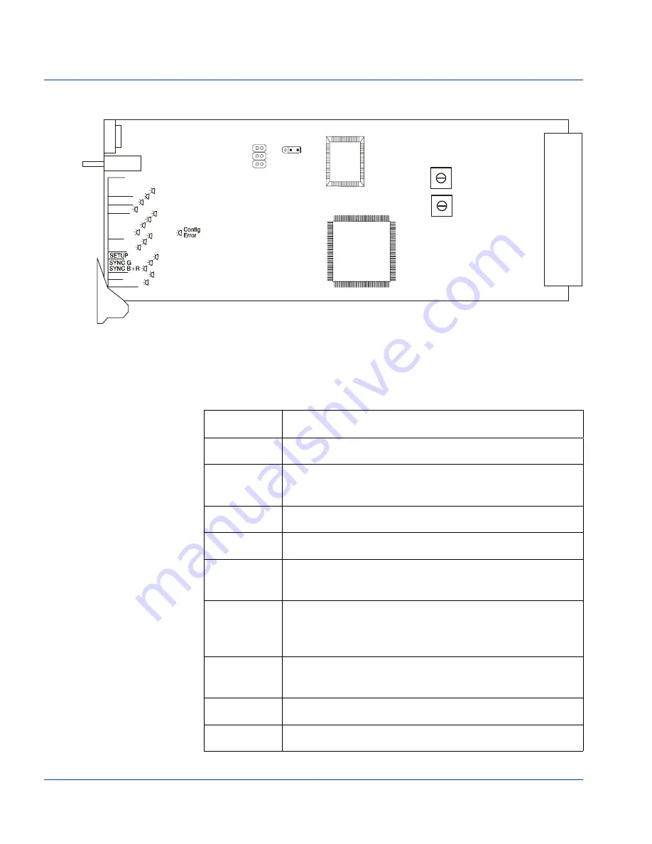
Figure 4-9.
Front Edge Switches/LEDs
LEDs
DAC-6801 LEDs illuminate as follows:
ACTIVITY
525
AUTO
625
ERROR
LOCK 1
GBR
Y, Pr, Pb
SMPTE
BETA
M-II
NTSC
DETENT
LOCK 1
LOCK
CB
Phase
CR
Phase
J1
J1
U14
System Firmware
Hex
Sw1
Toggle
Sw2
LEDs
Function
525
Indicates the module is running in 525 line mode.
AUTO
Indicates the module is running in AUTO mode: the line
mode is automatically changed as per the input signal.
625
Indicates the module is running in 625 line mode.
LOCK
Indicates the module is locked to the input serial video.
ERROR
Indicates the module has detected EDH errors in the input
serial video.
SMPTE,
BETA,
M-11, NTSC
Indicates the current analog level standard, generated at
output.
GBR and Y,
Pr, Pb
Indicates the current color matrix utilized.
SETUP
Indicates setup (pedestal) is added to output video.
SYNC G
Indicates sync inserted on G output in GBR mode.


