background image

PREFACE

This Operator’s Manual is meant for personnel that are

operating the machine and are responsible for its daily

maintenance.
Kindly read this manual fully prior to starting work.
Such instructions as are related to your safety and/or that of

others are marked in the margin by a warning triangle with

exclamation mark. These instructions should be observed

with particular care and attention.
Instructions which may lead to serious material damage in

case of non-compliance or incorrect use are marked in the

margin by an exclamation mark.
The machine described in this manual may contain compo-

nents which do not form part of the standard equipment but

are available as optional extras. This is not made clear in all

cases, because standard specifications may differ from

country to country.
Furthermore, machines and optional extras may be adjusted

to specific regional conditions whilst they are also subject to

permanent research and innovation. For this reason, the

specifications of your machine may not be consistent with the

pictures in this manual.

WARRANTY CONDITIONS

For those parts which fail in normal operating conditions the

factory will make replacement parts available, free of charge,

for a period of 6 (six) months from the date of purchase.

Warranty shall not apply if the instructions mentioned in this

manual have not been met, or if they have not been met

completely or correctly. Neither shall warranty apply in case

of modification of the machine by you or third parties

without our foreknowledge and/or authorisation.

TYPE- AND SERIAL NUMBER OF
YOUR MACHINE

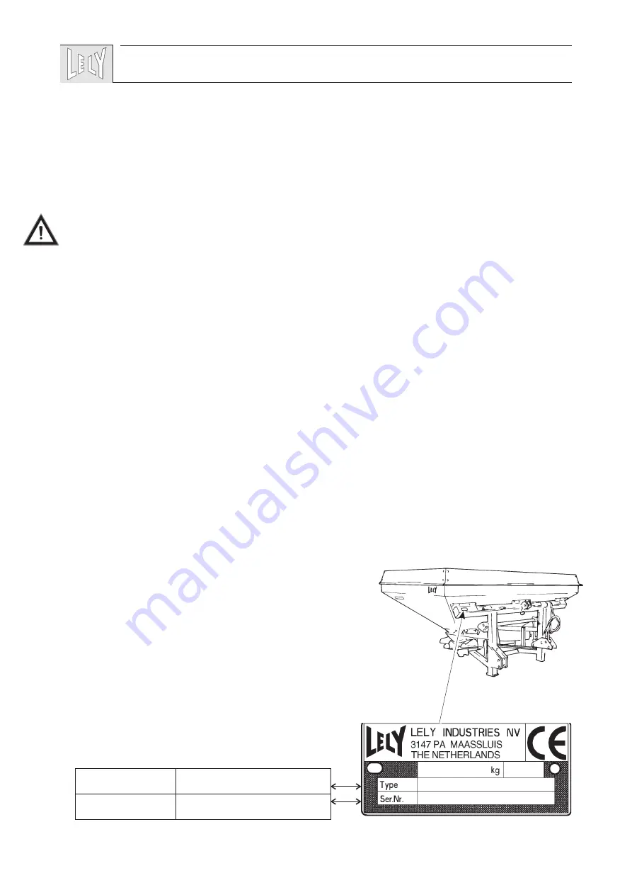
The type/serial number plate is fitted to the chassis beam at

the front of the machine.
In case of correspondence and ordering of spare parts, kindly

state the type- and serial number of your machine. Complete

the box below with these numbers.

37

!

type number

serial number

Summary of Contents for CENTERLINER S

Page 1: ...CENTERLINER S SL A HV 014 1198 O P E R A T O R S M A N U A L CENTERLINER S...

Page 2: ......

Page 3: ...ERMATIC are registrated trademarks The right of exclusive use belongs to the LELY companies 1998 All rights reserved Nothing of this publication may be reproduced and or published by printing photocop...

Page 4: ......

Page 5: ...ner discs speed 47 4 2 2 PTO output 48 4 2 3 Forward inclination 49 4 3 Working height 49 4 4 Tilting for headland spreading 50 5 WORKING WITH THE CENTERLINER 51 5 1 Working with the CENTERLINER S SL...

Page 6: ......

Page 7: ...tional extras may be adjusted to specific regional conditions whilst they are also subject to permanent research and innovation For this reason the specifications of your machine may not be consistent...

Page 8: ...the dangerous zone while the machine is in operation and be sure that people are kept well away from the machine This is especially important when working along roads and near or on fields that are a...

Page 9: ...s Danger of flying objects Keep a sufficient safe distance from the machine as long as the tractor motor is engaged Danger of rotating ejector discs Maintain a safe distance If the ejector discs are a...

Page 10: ...up by a 4 fold composite pattern fig 3 Because of its large working width as well as the varying working width of the S and SL version the CENTERLINER spreader is ideally suitable for following such t...

Page 11: ...2 3 4 spreading pattern LH ejector disc spreading pattern RH ejector disc combined CENTERLINER spreading pattern R R R R working width spreading width 100 50 50 50 R Working width R 2 2 5 m CENTRASID...

Page 12: ...nt the machine from making lateral movements Check the PTO shaft for smooth telescoping Mount the PTO shaft to the tractor PTO Before mounting the PTO shaft for the first time or when using another tr...

Page 13: ...mpty It is therefore recommended to fill the hopper after arrival on the plot to be worked This also eliminates the kind of fertilizer compression that may occur during transport It is possible to cou...

Page 14: ...fractions of the fertilizer to be applied fig 11 should therfore be compared to such fractions as are listed in the output chart The effective output may also be affected by other circum stances for...

Page 15: ...7 m Required forward speed V 8 km h Required output rate Q 475 kg ha Procedure Refer to working width chart for establishing the values for Z and H Z 23 12 H 5 Refer to the output chart to be used In...

Page 16: ...idth R 27 mm Required forward speed V 11km h Required output rate Q 280kg ha Procedure Consult the working width chart for values Z and H Z 23 12 H 5 Refer to the output chart to be used Divide 11 km...

Page 17: ...sets are indicated in the output charts by Z gear set top bottom When opening the gearbox for changing gears take care not to damage the sealing Example According to the sample chart fig 10 12 a gear...

Page 18: ...art Do not allow the spinner disc speed to exceed 1059 r p m as a result of an increased PTO speed If so required a PTO speed of 750 or 1000 r p m can be used as a means for saving fuel This can be ac...

Page 19: ...adland spreading Take tractor wheelings into account If fertilizer is thrown beyond the plot in case of smaller working widths and during headland spreading the PTO speed might be reduced and or the w...

Page 20: ...fig 16 Place the locking pin of the tumbler in hole D Couple the RH tractor lever arm to the machine hole A by means of the linkage pin Retract the ram again Headland spreading on the LH side of a plo...

Page 21: ...o await a windless day it is advisable not to choose an overly large working width Avoid working in lateral wind as much as possible Because of the large overlap of the spreading patterns the link up...

Page 22: ...nto the drive and PTO shaft This is of particular importance to tractors that are fitted with a hydraulic PTO coupling Then increase the PTO speed until your PTO speed is at the level required During...

Page 23: ...the headland end and close the shutters 5 3 Check of spreading width During spreading the fertilizer should roughly attain the preceding track only for working widths up to approx 21 m that do not req...

Page 24: ...red forward speed Measure the distance of the fertilizer application Weigh the balance of fertilizer Determine the output of fertilizer per hectare by means of the formula below 10 000 quantity put ou...

Page 25: ...e B fig 21 and retract the ram totally This will eliminate corrosion of the piston rod Switch off the tractor engine Take the PTO shaft from the tractor PTO Place the PTO shaft in the parking chord fi...

Page 26: ...Check the condition of the spinner discs and spoons Damaged or worn spinner discs and or spoons may affect the spreading pattern when fitting spoons mind the correct position fig 20 Tighten the bolts...

Page 27: ...spoons When fitting spoons mind the correct position see fig 20 Tighten the bolts with a torque of 15 Nm 1 5 kgm as a maximum Check all bolts and nuts for tightness Tighten loose bolts nuts by applyi...

Page 28: ...control rod should always be adjusted at a length of 130 mm Both gates are opened to the same extent but at position 3B the shutters are not on a par with the points of the feed gates Untighten the bo...

Page 29: ...ning Checking of the central gearbox can be done after removing the change gear cover The correct oil level is exactly between the arrow and the brim of the change gearbox fig 28 If necessary fill up...

Page 30: ...Check the presence and condition of all safety decals fig 29 A P N 9 1170 0408 0 B P N 9 1170 0407 6 C P N 9 1170 0421 6 2x D P N 9 1170 0410 2 E P N 16 61 175 60 29 A C D C B E...

Page 31: ...re the correct height of the spinner discs over the ground or crop When spreading on headlands reduce height if the fertili zer is thrown over the side of the plot Adjust the forward inclination Use a...

Page 32: ...der can be increased Carrier The CENTERLINER spreader can be turned into a trailed type by placing the machine on a wheeled carriage which sub stantially reduces the bottom pressure of the tractor tyr...

Page 33: ...etween tractor and CENTERLINER spreader is often limited especially in case a CENTER MATIC weighing device is used For this purpose a special telescoping PTO shaft can be used The PTO shaft allows eas...

Page 34: ...m 93 100 113 126 127 Weight kg 290 320 350 380 400 PTO speed 540 1000 r p m Spinner disc speed 1059 r p m as a maximum Working width 6 36 m adjustable through change gears or PTO speed Linkage categor...

Reviews: