


5.4006.8501.0
B
4-4
4.2.1.4
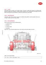
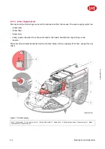
Water Supply System
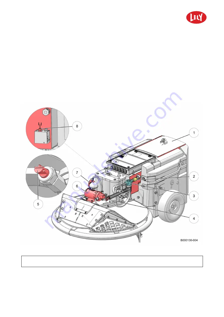
The nozzle on the front sprays water on the manure to soften the manure. The water supply system has:
•
Water inlet.
•
Water filter.
•
Water tank.
•
Pump, pumps the water from the water tank to the nozzle. Switched on only during a route.
•
Nozzle.
The water tank is balanced installed on the concrete block and has a capacity of 30 liter, enough for one
route.
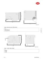
Figure 11. Water supply
KEY: 1. Water tank - 2. Non return valve - 3. Water filter (inlet) - 4. Water inlet - 5. Water spray nozzle - 6. Water pump - 7. Water
filter (outlet) - 8. Water sensor
in n o vato rs in ag ric u ltu re
Summary of Contents for Lely Discovery 90 SW
Page 2: ...INTENTIONALLY BLANK 5 4006 8501 0 B innovators in agriculture ...
Page 6: ...INTENTIONALLY BLANK 5 4006 8501 0 B 6 List of Included Amendments innovators in agriculture ...
Page 16: ...INTENTIONALLY BLANK 5 4006 8501 0 B 1 2 Lely Discovery innovators in agriculture ...
Page 62: ...INTENTIONALLY BLANK 5 4006 8501 0 B 4 36 Description and Operation innovators in agriculture ...
Page 98: ...INTENTIONALLY BLANK 5 4006 8501 0 B 5 36 Operating Instructions innovators in agriculture ...
Page 124: ...INTENTIONALLY BLANK 5 4006 8501 0 B 7 8 Test and Adjustment innovators in agriculture ...
Page 146: ...INTENTIONALLY BLANK 5 4006 8501 0 B 9 2 Disposal innovators in agriculture ...
Page 149: ......