innovators in agriculture
EN-9
2 LINKAGE TO THE TRACTOR
Link the machine to the tractor as follows:
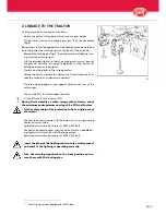
- Adjust the tractor’s three-point-hitch arms at equal height.
- Fit the lower arms to the linkage pins (cat II) of the headstock
(fig.4).
Better access to the linkage points of the headstock can be obtained
by turning away the warning signs at the front of the machine.
- Remove the locking pins (fig. 4) from the pivot points before turn-
ing away the warning signs.
- Lift the drawbar slightly so that the parking jacks are just clear of
the ground. Maintain this height adjustment of the tractor lift
during operation and transport.
- Place the parking jacks in the raised position.
- Secure the tractor’s lower arms by means of stabilisation chains or
rods to eliminate any sideways movements.
- Place the wheel wedges in the supports fitted on the rear of the
safety signs.
- Check if the PTO shaft telescopes smoothly.
- Fit the PTO shaft to the tractor PTO.
During first assembly or when using another tractor, check
the minimum and maximum overlap of the PTO shaft halves
*
.
- Fit the safety chain of the protection tube to a rigid part of
the tractor.
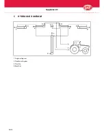
- Connect the hydraulic hose with the blue mark to a single-acting
hydraulic tractor valve.
Permitted maximum oil pressure: 21.0 MPa (210 bar).
- Connect the hydraulic hoses with the white mark to a double-act-
ing hydraulic tractor valve with floating position.
Permitted maximum oil pressure: 21.0 MPa (210 bar).
- Insert the plug of the lighting cable into the tractor socket
and check if the lighting is operating correctly.
- Turn the warning signs back to the front position and se-
cure them with the locking pins.
*. Consult the instructions supplied with the PTO shaft
4
A
!

