12
Adjusting the input signal
Setting the input signal of a digital unit is particularly important, much more than with an analog unit, as
any saturation of the A/D converters caused by excessively high input signals cause a typical particu-
larly distinct noise (high level square wave).
Proceed as follows:
☞
Keep the DX 24 outputs in MUTE status (LEDs lit).
☞
Feed a signal in on the DX 24’s input and watch the INPUT LEVEL A-B LED ladders.
To obtain a good signal/noise ratio, i.e. an up-front distortion-free signal, keep the signal quite high, but
make certain the red CLIP LED doesn’t light up continually.
☞
First of all, find the output level setting for your mixer (or other unit) connected to the input of the DX 24
☞
Then adjust the DX 24 input gain if necessary:
Press the MODE key until the EDIT menu LED lights up.
Use the PREV and NEXT keys to go to the Input Gain page:
Ò
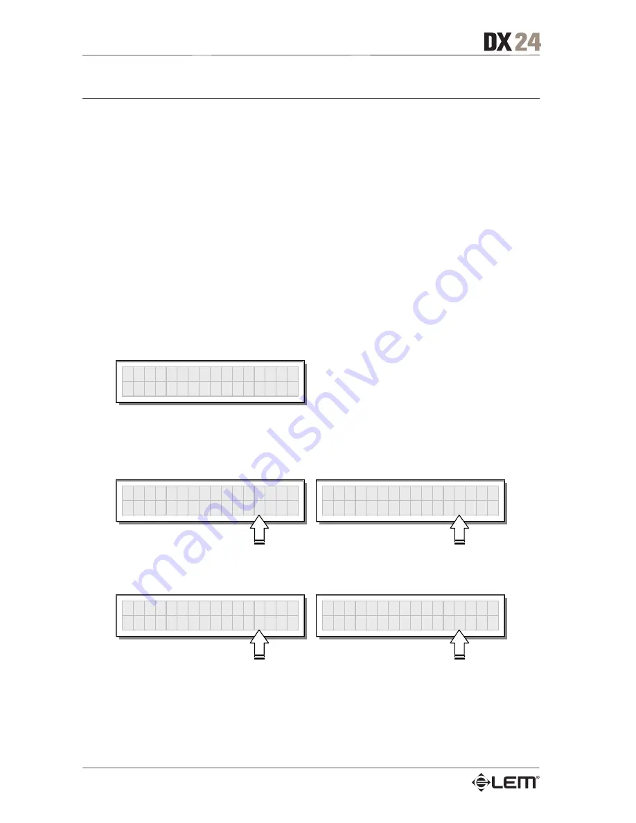
I n p u t G a i n
Press ENTER. The display shows the INA Gain or INA&B Gain page (according to the configuration
and other utilities loaded in the memory):
I N A
G A I N
0 . 0 d B
I N A & B G A I N
0 . 0 d B
Use the DIAL to change the gain value and watch the level of the signal on the LED ladders until the
ideal values are reached.
I N A
G A I N
- 2 . 5 d B
I N A & B G A I N
+ 6 . 0 d B
Then use the PREV and NEXT keys to access the INB Gain page (if there is one – this depends on the
configuration and the other utilities loaded in the memory).
Repeat the settings as explained above.
Getting Started
Summary of Contents for DX 24
Page 1: ......
Page 50: ...48 Configurations...
Page 52: ...50 Connections...
Page 53: ...51 Connections...
Page 54: ...52 Connections...
Page 55: ...53 Communications PC one or more DX 24 connection Connections...
Page 56: ...54 Communications two or more DX 24 short distance connection Connections...


