background image

LEMA Off-Grid User Manual (DM-003-A) 
© 2021 LEMA - lema.io 
Saint Paul, Minnesota, USA


Page | 

53


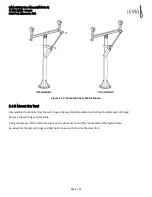
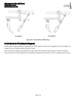
Figure 5-21 - Mounted Linear Motor Day 

5.4.10


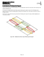
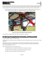
Attach the PV Racking Yard Supports 

Remove and set aside the (18x) pre-installed 10-32 X 0.5IN LG bolts on the four mounting points of the Yard. (Note, the 
tapped holes on the Yard and Mast use #10-32 thread.) 

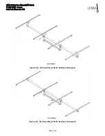
Attach the four PV Racking Yard Supports to the Yard. (Orient the PV Racking Yard Supports as shown in the figures 
below. Pay attention to the location of the PV Racking Yard Supports relative to the four mounting points on the Yard.) 

Summary of Contents for LOG-0001-A

Page 1: ...LEMA Off Grid User Manual Business Plan Document Number DM 003 A WTS LLC 275 East 4th Street Suite 720 Saint Paul MN 55101 USA www lema io June 2021 DM 003 A LEMA Off Grid User Manual...

Page 2: ...12 3 2 Linear Motor Season 12 3 2 1 Hardware 13 3 3 Linear Motor Day 14 3 3 1 Hardware 14 3 4 Footing 15 3 4 1 Sonotube 16 3 4 2 PVC Tubing 16 3 4 3 Hardware 17 3 5 PV Racking 17 3 5 1 PV Racking Supp...

Page 3: ...ler 43 5 4 1 Setup LEMA Off Grid Electrical Enclosure 43 5 4 2 Electrical Connections Between Solar Tracker and Base of LEMA Off Grid Electrical Enclosure 44 5 4 3 Bury the 8 Copper Ground Rod 46 5 4...

Page 4: ...Tracker Automation Button Commands 90 7 2 2 Solar Tracker Photovoltaic Disconnect Switch 91 7 3 Primary Operation of the LEMA Electrical Enclosure 91 7 3 1 Toggling Outlet 1 and Outlet 2 via External...

Page 5: ...Battery 23 Figure 3 19 Upper Battery Cables 23 Figure 3 20 Lower Battery Cables 24 Figure 3 21 Lower Battery Mounts 24 Figure 3 22 Upper Battery Hold Down Bolts 25 Figure 3 23 Victron Energy MultiPlus...

Page 6: ...54 Figure 5 23 Post Assembly of the PV Racking Yard Supports 54 Figure 5 24 Pre Assembly of the PV Racking Side Supports 55 Figure 5 25 Post Assembly of the PV Racking Side Supports 56 Figure 5 26 Id...

Page 7: ...Upper Battery Mounts During Shipping 79 Figure 5 62 Empty Battery Enclosure 79 Figure 5 63 Insert the Bottom Plate 80 Figure 5 64 Install Battery BAT 101 80 Figure 5 65 Install Battery BAT 102 81 Figu...

Page 8: ...ose WTS may make improvements and or changes in this manual or in the product s and or the program s described in this manual at any time This product is still in its prototyping phase all information...

Page 9: ...4KWh or 8KWh battery storage charge controls and a 2KW inverter providing 230VAC electricity out of two independently controllable outlets The system ships with a 25HP pump kit which includes a float...

Page 10: ...ft x 5 ft 0 60 m x 0 91m x 1 52 m Enclosure Weight 160 lbs 72 57 kg Battery Weight 4 x 60 lbs 27 21 kg 240 lbs 108 86 kg Power Supply None Controls Power Consumption 100 watts peak 10 watts average O...

Page 11: ...Saint Paul Minnesota USA Page 11 3 System Components The following material in this section describes the major parts shipped with the system 3 1 Mechanical System Figure 3 1 Mechanical System 3 1 1...

Page 12: ...4 Yard 3 1 4 Hardware 1x Shoulder bolt o Pre Installed 1x Shoulder bolt NUT o Pre Installed 3 2 Linear Motor Season Two stepper motors with 15 1 gearboxes and linear lead screws One runs the day axis...

Page 13: ...Paul Minnesota USA Page 13 Figure 3 5 Linear Motor Season 3 2 1 Hardware 2x 18 8 Stainless Steel Shoulder Bolt M10 1 50 12mm OD 16mm Shoulder LG o Attached to Linear Motor Season 1x Threadlocker Loct...

Page 14: ...Minnesota USA Page 14 3 3 Linear Motor Day Figure 3 6 Linear Motor Day 3 3 1 Hardware 2x 18 8 Stainless Steel Shoulder Bolt M10 1 50 12mm OD 16mm Shoulder LG o Attached to Linear Motor Day 1x Threadlo...

Page 15: ...LEMA Off Grid User Manual DM 003 A 2021 LEMA lema io Saint Paul Minnesota USA Page 15 3 4 Footing Figure 3 7 Footing...

Page 16: ...LEMA Off Grid User Manual DM 003 A 2021 LEMA lema io Saint Paul Minnesota USA Page 16 3 4 1 Sonotube Figure 3 8 Sonotube 3 4 2 PVC Tubing Figure 3 9 PVC Tubing...

Page 17: ...Saint Paul Minnesota USA Page 17 3 4 3 Hardware 8x 1 2 13 Thin Hex Nut Grade 5 Steel Zinc Plated o Pre Installed 8x 1 2 Washer Flat 0 531 ID 1 062 OD 0 177 Thick Grade 8 Steel Zinc Aluminum Coated o...

Page 18: ...t PV panels This mounts on top of the Yard Figure 3 11 PV Racking Supports 3 5 2 PV Solar Panels LG s latest bi facial solar panels absorb the sun s energy on the front and back faces of the solar pan...

Page 19: ...BLIND RIVET 3 16 OD 0 251IN TO 0 375IN MAT 39x M5X0 8MM X 12MM LG BHCS S TORX T25 o 6x Pre Installed on PV Switch Enclosure 33x M5 0 8MM EXTERNAL TOOTH LOCKNUT 18x 10 32 X 0 5IN LG BHCS S TORX T25 o P...

Page 20: ...4x M5 0 8MM x 60MM Lg 18 8 Stainless Steel Hex Drive Rounded Head Screw o Attached to Solar Tracker Controller 3 7 LEMA Off Grid Electrical Enclosure The housing for the electrical controls system inv...

Page 21: ...LEMA Off Grid User Manual DM 003 A 2021 LEMA lema io Saint Paul Minnesota USA Page 21 Figure 3 16 LEMA Off Grid Electrical Enclosure...

Page 22: ...ny 12v lead acid battery alternatives which can be used for example car batteries boat batteries etc the Victron Charge Controller supports many types of batteries see the Victron Charge Controller ma...

Page 23: ...ad Acid Battery 3 7 2 Battery Cables Battery Cables to connect the Batteries together in series The cables are numbered to match the electrical terminal on the battery which they are supposed to be co...

Page 24: ...t Paul Minnesota USA Page 24 Figure 3 20 Lower Battery Cables 3 7 3 Lower Battery Mounts Battery mounts to secure the lower batteries in place Figure 3 21 Lower Battery Mounts 3 7 4 Upper Battery Hold...

Page 25: ...battery energy into 230 VAC energy which can be used by electrical equipment The model is a Victron Energy Easy Solar II Figure 3 23 Victron Energy MultiPlus II 3 7 6 Charge Controller The charge con...

Page 26: ...the following image This device has an automation hat on it The computer system controls the outlets runs the Home Assistant software monitors the Victron equipment and monitors the float switch Figur...

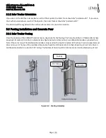
Page 27: ...0VDC This circuit breaker disconnects the Charge Controller from the 48VDC battery power rail 80 AMP 150VDC This circuit breaker disconnects the battery 48VDC power rail from the power input to the In...

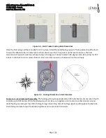
Page 28: ...AGM Battery 12V 100Ah 1x Battery Cable 119 1x Battery Cable 117 1x Battery Cable 115 3 8 Pump Pump Float 3 8 1 Pump Float Encased within the Pump Float is the Pump The yellow connector is the electric...

Page 29: ...LEMA Off Grid User Manual DM 003 A 2021 LEMA lema io Saint Paul Minnesota USA Page 29 Figure 3 28 Pump Float 3 8 2 Pump Cable Figure 3 29 Pump Cable...

Page 30: ...ate the pumping system The Pump Float Switch is mounted inside of a tank which is to be filled by water from the Pump Float When the tank fills above the fixed height of the Pump Float Switch the Pump...

Page 31: ...Ground Rod 1x 1 2 Grounding Rod Clamp 1x 10AWG PV Wire Black 36ft 11m 1x 10AWG PV Wire Red 36ft 11m 2x 10AWG PV Wire Black 12 5ft 3 8m 1x 10AWG PV Wire Black 2ft 0 6m 1x Grounding Wire Green 36ft 11m...

Page 32: ...LEMA Off Grid User Manual DM 003 A 2021 LEMA lema io Saint Paul Minnesota USA Page 32 3 11 Tool Kit Spare Parts 3 11 1 Tool Kit Setup and assembly to tools for the LEMA Off Grid Figure 3 33 Tool Kit...

Page 33: ...l 1423 1 4 Heavy Duty 13 Hand Riveter 1x 1 8 Precision Screwdriver Set 6 Piece 1x Adjustable Wrench Set 3 Piece 1x Low Profile Right Angle 1 4 Ratchet Set 1x 1 4 3 8 Drive SAE Metric Mechanic s Tool S...

Page 34: ...2021 LEMA lema io Saint Paul Minnesota USA Page 34 4 Packaging Figure 4 1 Packaged Sealed LEMA Off Grid Shipping Boxes 4 1 Box 1 of 5 Contains LEMA Off Grid Electrical Enclosure Box 5 of 5 Box 3 of 5...

Page 35: ...LEMA Off Grid User Manual DM 003 A 2021 LEMA lema io Saint Paul Minnesota USA Page 35 Figure 4 2 Box 1 of 5 4 2 Box 2 of 5 Contains Yard PV Racking Supports Linear Motor Season Linear Motor Day...

Page 36: ...MA Off Grid User Manual DM 003 A 2021 LEMA lema io Saint Paul Minnesota USA Page 36 Figure 4 3 Box 2 of 5 4 3 Box 3 of 5 Contains PV Solar Panels Figure 4 4 Box 3 of 5 4 4 Box 4 of 5 Contains Batterie...

Page 37: ...aint Paul Minnesota USA Page 37 Figure 4 5 Box 4 of 5 4 5 Box 5 of 5 Contains Footing Mast Goal Post PV Disconnect Switch Tool Kit Spare Parts Pump Pump Float Pump Float Switch Mechanical Structure PV...

Page 38: ...rid User Manual DM 003 A 2021 LEMA lema io Saint Paul Minnesota USA Page 38 4 5 1 Box 5 of 5 Lower Section Figure 4 6 Box 5 of 5 Lower Section 4 5 2 Box 5 of 5 Upper Section Figure 4 7 Box 5 of 5 Uppe...

Page 39: ...cal Enclosure 5 Route electrical cables and assemble LEMA Solar Tracker on Footing 6 Install batteries in LEMA Off Grid Electrical Enclosure 7 Power System On 8 Use external button to enable power out...

Page 40: ...lar Tracker Footing Once the location of the LEMA Off Grid is chosen dig a hole for the footing The hole should be 1 17 Meters 46 inches deep by 0 41 meters 16 inches in diameter see figure below for...

Page 41: ...rotated in 90 degree intervals to allow for PVC cutout in structure to be in correct direction Once concrete is poured structure will not move freely Figure 5 4 Footing Orientation in hole concrete C...

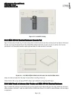
Page 42: ...ed Pad will require approximately 0 1 cubic meters of concrete Figure 5 6 5 3 2 LEMA Off Grid Electrical Enclosure Concrete Pad Dimensions Allow concrete to harden for five days to cure before mountin...

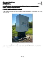
Page 43: ...5 4 1 Setup LEMA Off Grid Electrical Enclosure Remove the LEMA Off Grid Electrical Enclosure from Box 1 of 5 and setup the LEMA Off Grid Electrical Enclosure on the cured concrete pad Figure 5 7 LEMA...

Page 44: ...ical Enclosure Base Rear Cover Bolt Locations Figure 5 9 LEMA Off Grid Electrical Enclosure Base Rear Cover Removed 5 4 2 Electrical Connections Between Solar Tracker and Base of LEMA Off Grid Electri...

Page 45: ...ata Cable 42ft 12 8m Figure 5 10 Cable Bundle Between Solar Tracker and LEMA Off Grid Electrical Enclosure Connect the Red Male MC4 connector of the 1x 10AWG PV Wire Black 36ft 11m 1x 10AWG PV Wire Bl...

Page 46: ...connector located on the top plate within the back panel Figure 5 12 Solar Tracker Power and Data Cable Connector Route the wires in the open trench between the Solar Tracker and Base of LEMA Off Grid...

Page 47: ...ound Rod into the soil until about 1in 2 5cm of the 8 Copper Ground Rod remains above the surface Figure 5 13 8 Copper Ground Rod Location Note The grounding cables are not connected at this point of...

Page 48: ...m 1x 10AWG PV Wire Red 36ft 11m 1x 10AWG PV Wire Black 12 5ft 3 8m 1x Solar Tracker Controller Power Data Cable 42ft 12 8m Route the 1x Copper Braid 20ft 6m through the Mast from bottom to the top esc...

Page 49: ...LEMA Off Grid User Manual DM 003 A 2021 LEMA lema io Saint Paul Minnesota USA Page 49 Figure 5 16 Align Mast North South Figure 5 17 Align the Lower Linear Motor Season Mounting Point North South...

Page 50: ...8 Goal Post mount on Mast 5 4 7 Attach the Linear Motor Season Locate the Linear Motor Season the Linear Motor Season is labeled Season Axis near the electrical connector Remove the taped on shoulder...

Page 51: ...the Yard Disassemble the 8x bolts from the split ring on the Goal Post be careful not to drop the bolts and split rings Remove the split rings and set aside Using two people lift the Yard into place o...

Page 52: ...Linear Motor Day Locate the Linear Motor Day the Linear Motor Day is labeled Day Axis near the electrical connector Remove the taped on shoulder bolts and thread locker Loctite 243 from the Linear Mot...

Page 53: ...aside the 18x pre installed 10 32 X 0 5IN LG bolts on the four mounting points of the Yard Note the tapped holes on the Yard and Mast use 10 32 thread Attach the four PV Racking Yard Supports to the Y...

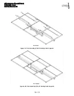
Page 54: ...LEMA Off Grid User Manual DM 003 A 2021 LEMA lema io Saint Paul Minnesota USA Page 54 Figure 5 22 Pre Assembly of the PV Racking Yard Support Figure 5 23 Post Assembly of the PV Racking Yard Supports...

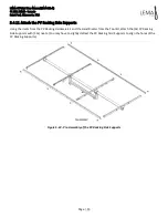
Page 55: ...Supports Using the rivets from the PV Racking Hardware kit and the Hand Riveter from the Tool Kit attach the 2x PV Racking Side Supports with 32x rivets You may have to slightly deflect the PV Rackin...

Page 56: ...LEMA Off Grid User Manual DM 003 A 2021 LEMA lema io Saint Paul Minnesota USA Page 56 Figure 5 25 Post Assembly of the PV Racking Side Supports...

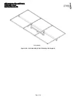
Page 57: ...48x rivets You may have to slightly deflect the PV Racking Yard Side Supports to align the holes of the PV Racking Center Supports Be sure to orient the PV Racking Center Supports and install the rive...

Page 58: ...MA Off Grid User Manual DM 003 A 2021 LEMA lema io Saint Paul Minnesota USA Page 58 Figure 5 27 Pre Assembly of the PV Racking Center Supports Figure 5 28 Post Assembly of the PV Racking Center Suppor...

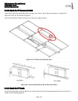
Page 59: ...e Kit attach the PV Disconnect switch to the PV Racking Supports Orient and locate the PV Disconnect Switch as shown in the figures below Figure 5 29 PV Disconnect Switch Location Figure 5 30 Pre Post...

Page 60: ...anels to add a small gap between the center PV panel and outer PV Panels to allow rainfall to shed between the PV Panels Locate the PV Panel Junction Box on the side of the PV Racking nearest the PV D...

Page 61: ...Saint Paul Minnesota USA Page 61 Figure 5 32 Pre Assembly of the PV Panels Figure 5 33 Post Assembly of the PV Panels Using the 3x M5 bolts and 3x M5 External Tooth Locknuts Attach the 3x PV Panel alu...

Page 62: ...LEMA Off Grid User Manual DM 003 A 2021 LEMA lema io Saint Paul Minnesota USA Page 62 Figure 5 34 PV Panel Aluminum Grounding Lug Locations...

Page 63: ...EMA Off Grid User Manual DM 003 A 2021 LEMA lema io Saint Paul Minnesota USA Page 63 Figure 5 35 PV Panel Aluminum Grounding Lug Location Right Figure 5 36 PV Panel Aluminum Grounding Lug Location Lef...

Page 64: ...e for wiring remove the 6x M5 bolts on the PV Disconnect Switch Cover and set aside Figure 5 37 PV Disconnect Switch Cover Bolt Locations Pre Disassembly Figure 5 38 Post Disassembly PV Disconnect Swi...

Page 65: ...taped to the Solar Tracker Controller attach the Solar Tracker Controller to the Goal Post Orient the Solar Tracker Controller with the connected cables closest to the Linear Motor Day as shown in th...

Page 66: ...Tracker Controller A Solar Tracker Controller Power Data Cable a Season Axis cable a Day Axis cable and a Day Limit Switch cable Figure 5 41 Solar Tracker Controller Cables Connect the Season Axis Cab...

Page 67: ...n Routing Path The Solar Tracker Controller Power Cable will be connected in the next section 5 5 2 Wire Copper Grounding Braid Solar Track Controller and PV Disconnect Switch Turn the PV Disconnect S...

Page 68: ...es will be coming out of the hole in the top of the mast Connect the 1x Solar Tracker Controller Power Data Cable 42ft 12 8m to the Solar Track Controller as shown Be sure to include a small loop of e...

Page 69: ...re Black 12 5ft 3 8m 1x 10AWG PV Wire Red 36ft 11m 1x 10AWG PV Wire Black 12 5ft 3 8m 1x Copper Braid 20ft 6m Figure 5 44 Wire Routing along the Goal Post Yard and PV Racking Route the 1x Copper Braid...

Page 70: ...Panel 1 Route and connect the following wires to the PV Disconnect Switch as shown in the figure below The male and female MC4 connectors on the cables correspond to the mating male and female MC4 con...

Page 71: ...Green 36ft 11m to the 8 Copper Ground Rod using the 1 2 Grounding Rod Clamp as shown in the figure below Feel free to cut remove or bundle excess Copper Braid after operation of the Solar Track has b...

Page 72: ...connect the wires of the PV Panels in series from the left to the right as shown in the figure below Use the 10AWG PV Wire Black 2ft 0 6m to extend the positive leg of PV Panel 3 to reach the PV Disco...

Page 73: ...1 LEMA lema io Saint Paul Minnesota USA Page 73 Figure 5 51 PV Panel 3 Wire Routing Figure 5 52 PV Panel 2 and PV Disconnect Switch Wire Routing PV Panel 2 PV Panel 1 PV Panel 3 144VDC PV Panel 3 DC C...

Page 74: ...inside of the PV Disconnect Switch enclosure as shown in the figure below Figure 5 53 Tighten Zip Ties Remove Excess Zip Tie Material Re install the PV Disconnect Switch Cover as shown below in the f...

Page 75: ...EMA Off Grid User Manual DM 003 A 2021 LEMA lema io Saint Paul Minnesota USA Page 75 Figure 5 55 Completed Mechanical Structure Wiring Orthogonal Figure 5 56 Completed Mechanical Structure Wiring Side...

Page 76: ...e Solar Tracker or LEMA Off Grid Electrical Enclosure In that case simply coil the extra cable up zip tie it together and leave it inside the base of the LEMA Off Grid Electrical Enclosure 5 6 Install...

Page 77: ...LEMA Off Grid User Manual DM 003 A 2021 LEMA lema io Saint Paul Minnesota USA Page 77 Figure 5 58 Upper Circuit Breakers Figure 5 59 Lower Circuit Breaker 15A 30A 80A 20A AC 4A...

Page 78: ...ry Mounts should be the only floating loose cables The batteries are labeled BAT 101 BAT 102 BAT 103 and BAT 104 The cables and battery terminals are also labeled For example a Battery Cable labeled 1...

Page 79: ...SA Page 79 Figure 5 61 Secured Battery Cables and Upper Battery Mounts During Shipping Figure 5 62 Empty Battery Enclosure There is a blue bottom plate which needs to be manually placed This plate sta...

Page 80: ...llowing picture illustrates placing battery 101 Figure 5 64 Install Battery BAT 101 Before physically pushing the battery all the way to the back as shown in the above image you need to set the batter...

Page 81: ...with tape or other rubber cover and have a second person assist to ensure the red terminal does not touch any metal components Install the second battery BAT 102 to the cabinet as shown in the follow...

Page 82: ...Battery Temperature Monitor In the above picture also connect the temperature sensor to the bolt and nut on terminal 101 8 The temperature sensor has a blue shrink wrap jack on it as shown above Secu...

Page 83: ...y Hold Down Bolts The final arrangement has all four batteries loaded in the shelving The electrical cables should be mounted on the appropriate battery terminals and the batteries should be anchored...

Page 84: ...rise of 100meters 5 7 1 Pump Pump Float Encased within the Pump Float is the Pump The yellow connector is the electrical connection point for the Pump Cable and the brass threaded pipe fitting is the...

Page 85: ...adaptor in your LEMA Off Grid kit The Pump Float is ready to be placed in the water Select a location in your water source where the Pump Float can stand upright and anchor the float in place if neede...

Page 86: ...with the location highlighted below Zip tie the Pump Float Switch to the base of the LEMA Off Grid Electrical Enclosure for strain relief as you route the Pump Float Switch Figure 5 73 Pump Float Swit...

Page 87: ...outer from the din rail mount Cut zip ties as needed Remove the screws in the mount to allow the Router to be freed from the mount The back of the Router has a cover which can slide of following the d...

Page 88: ...Unit Specific Checkout Sheet which contains settings and passwords which are specific to each LEMA Off Grid serial numbered unit These details are secrets which cannot be included in this document Yo...

Page 89: ...ts on the Nighthawk Router and Raspberry Pi are illuminated o The automation hat on the Raspberry Pi hat will show a blue flashing LEG indicating software is running Flip the 20A AC circuit breaker fo...

Page 90: ...ated where the Season Axis points to the end of its travel toward zenith and the Day Axis jogs to 90 degrees The Sleep position is the hardware s center of gravity pointing straight up to the sky The...

Page 91: ...utton Toggle Outlet 1 o Outlet 1 is on the bottom left side of the unit Electrical Enclosure This is designed to run the high power load This is where you connect the pump o Tap the button to toggle O...

Page 92: ...ware running on the Raspberry Pi which is stored on an SD Card A spare SD Card with the system image written onto it was shipped in the spare parts kit for the device The Victron Energy devices also h...

Page 93: ...t via WiFi The Router also enables a user to communicate with the LEMA Off Grid Controls System from a web browser or via the Home Assistant app which runs on Android and iOS cell phones The LEMA Off...

Page 94: ...pberry Pi has a static IP address of 192 168 10 2 When connect to the WiFi provided by the Netgear Router a user can use the Home Assistant Phone App or simply point a browser at the service which is...

Page 95: ...LEMA Off Grid User Manual DM 003 A 2021 LEMA lema io Saint Paul Minnesota USA Page 95...

Page 96: ...ows a user to control the system from a phone or computer via a web browser or via the Home Assistant app which runs on Android and iOS 10 1 Home Assistant Pages The first step is to install the Home...

Page 97: ...e Detail tab on the top allows you to see many more telemetry parameters from the system The History tab shows parameter telemetry through time These charts are configurable you can for example change...

Page 98: ...Continued 10 2 Remote Connectivity via Nabu Casa Web Service To connect to a LEMA Off Grid Home Assistant instance from a remote location over the internet a LEMA Off Grid customer needs to setup a N...

Page 99: ...LEMA Off Grid User Manual DM 003 A 2021 LEMA lema io Saint Paul Minnesota USA Page 99...

Page 100: ...11 Electrical One Line Diagram The following image is an electrical one line diagram showing how power flows through the LEMA Off Grid system...

Page 101: ...LEMA Off Grid User Manual DM 003 A 2021 LEMA lema io Saint Paul Minnesota USA Page 101...

Page 102: ...M 003 A 2021 LEMA lema io Saint Paul Minnesota USA Page 102 12 Electrical Drawing The complete electrical drawing of the LEMA Off Grid system is delivered as a separate PDF This is included in your di...

Reviews: