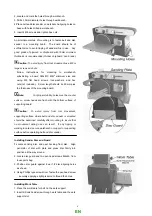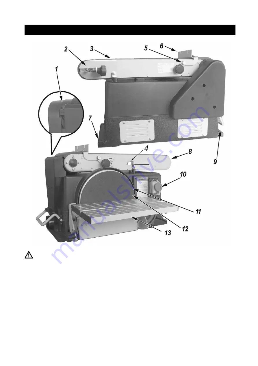
GETTING TO KNOW YOUR BELT & DISC SANDER
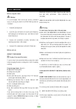
Warning:
To avoid injury from accidental start, remove the plug from
power source outlet before making any adjustments.
1.
Hex socket head screw.
Loosening screw allows belt bed
to raise to the vertical position.
2.
Tracking knob.
Turning knob counterclockwise causes
sanding belt to move towards the disc; otherwise to move
away from the disc
3.
Sanding belt.
4.
Tension lever
. Sliding lever to the right releases the
sanding belt tension; sliding lever to the left applies belt
tension.
5. Work support hex screw.
6.
Work support.
Supports the workpiece on the sanding
belt.
7.
Base
8.
Belt bed.
9.
Mounting holes.
10. No-volt switch
11.
Sanding Disc.
12.
Sanding paper.
13.
Work table assembly.
9
EN
Summary of Contents for BDS610
Page 2: ......
Page 3: ...Manuel d utilisation MODELE PON250 FR...
Page 19: ...17 13 2 Vue clat e de la machine FR...
Page 22: ...Manual de instrucciones MODELO PON250 ES...
Page 41: ...20 14 DESPIECE ES...
Page 42: ...21 ES...
Page 67: ...Diagram 21 EN...
Page 68: ...Notes...
Page 69: ......


