Commissioning
15
Pos. #
Symbol
PIN
Signal
(lead co-
lour)
Function
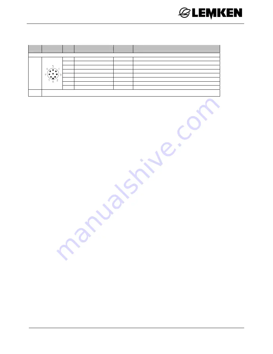
CAN2-IN / M12 x1 – 8-pin plug
1
+12V / +24V
White
Supply (+UB)
2
Emergency Stop
Brown
Hardware Emergency Stop, jumped to PIN 4
3
Cut-in signal
Green
Cut-in signal for control units (+UB switched)
4
Emergency Stop
Yellow
Hardware Emergency Stop, jumped to PIN 2
5
CAN2-L
Grey
CAN bus Low
6 GND
Pink
Supply
ground
7
CAN2-H
Blue
CAN bus High
3
8 Screen
Red
Screen
capacitively decoupled
8
WLAN aerial – SMA socket
( ) – only available for connectors with strands
3.5 Connecting the terminal
For connection to the ISOBUS a special cable set is required, which can be or-
dered by quoting the LEMKEN article number 573 6204.
Perform the steps in the following sequence.
Choose a suitable position in the tractor cab (in driver's field of vision) where you wish to mount
the terminal.
Mount the terminal using the device holder into the tractor cab.
Connect the terminal to the 9-pin ISOBUS socket.
Connect the terminal to the 7-pin signal socket.


