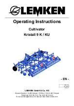
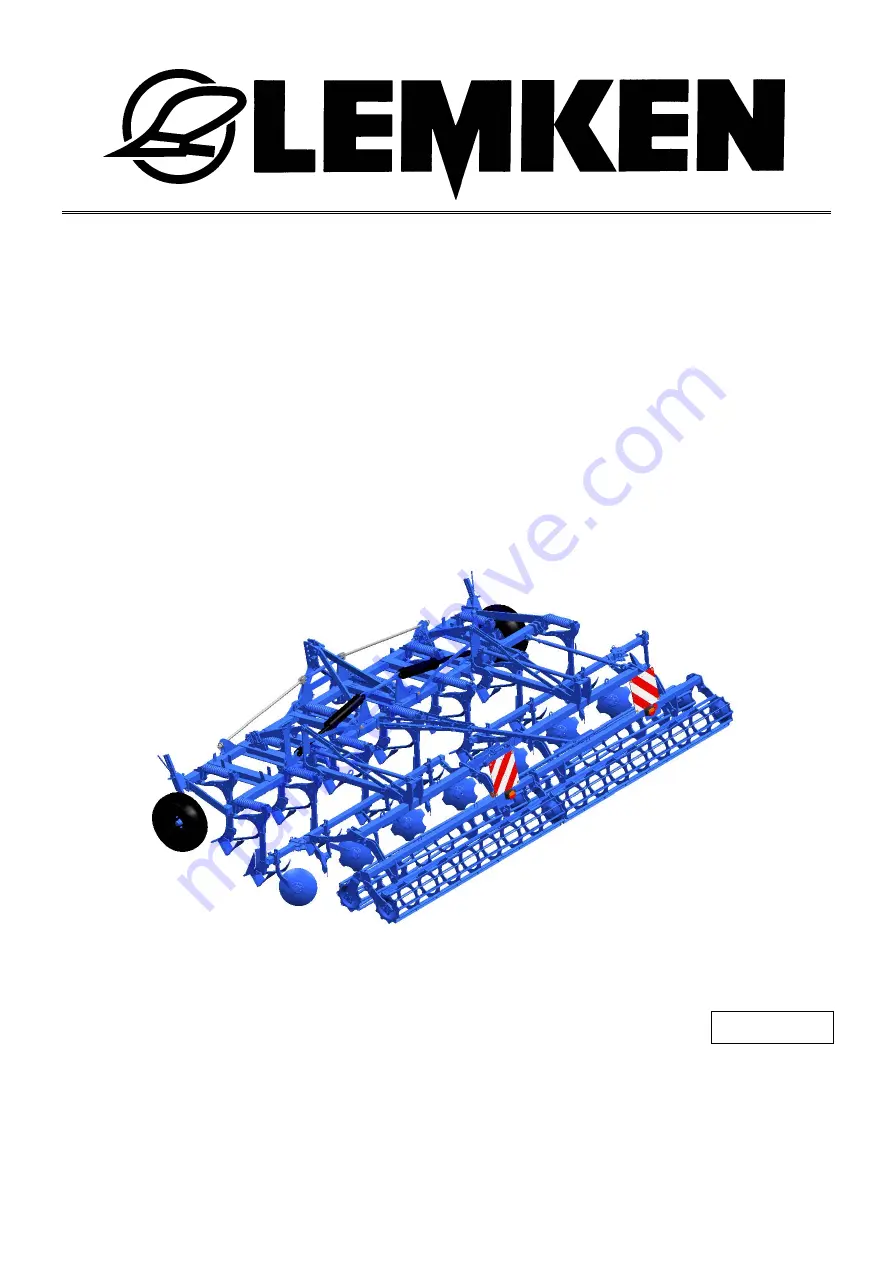
LEMKEN Kristall 9 K, Operating Instructions Manual
The LEMKEN Kristall 9 K is a powerful cultivator designed for efficient soil preparation. Ensure optimal performance by referring to the Operating Instructions Manual available for free download from our website. This manual provides detailed guidance on how to operate and maintain your cultivator. Download it now!
Share
Download


Reviews:
No comments
Related manuals for Kristall 9 K

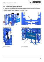
700
Brand: Salford Pages: 64

60 Series
Brand: Tar River Pages: 27

C2000
Brand: Camon Pages: 2

Y Series
Brand: Barreto Pages: 18

450 Series
Brand: Yard Machines Pages: 20

FC10
Brand: Land Pride Pages: 24

30
Brand: Yard Machines Pages: 16

SP05
Brand: Baroness Pages: 12

3365B
Brand: EarthQuake Pages: 28

3365 Series
Brand: EarthQuake Pages: 24

TC-210i
Brand: Echo Pages: 18

TA21
Brand: Lawn Solutions Pages: 14

MB5000
Brand: Nakayama Pages: 49

7155
Brand: EarthQuake Pages: 36

YT5601-01
Brand: YAT Pages: 61

VERSA Series
Brand: EarthQuake Pages: 13

RT65
Brand: Yard-Man Pages: 20

PRO MB6510
Brand: Nakayama Pages: 49


