background image

LEMKEN GmbH & Co. KG

Weseler Straße 5, D-46519 Alpen / Postfach 11 60, D-46515 Alpen

Telefon (0 28 02) 81-0, Telefax (0 28 02) 81-220

E-Mail: lemken@lemken.com, Internet: http://www.lemken.com

Art.-Nr.: 175 3801

GB-1/08.04

          SAFETY IS OUR CONCERN!

Operating 

Instructions

Cultivators

Thorit 9 K

Summary of Contents for Thorit 9 K

Page 1: ... D 46519 Alpen Postfach 11 60 D 46515 Alpen Telefon 0 28 02 81 0 Telefax 0 28 02 81 220 E Mail lemken lemken com Internet http www lemken com Art Nr 175 3801 GB 1 08 04 SAFETY IS OUR CONCERN Operating Instructions Cultivators Thorit 9 K ...

Page 2: ......

Page 3: ...nges and modifications carried out not being mentioned expressly in this instruction book may only be carried out with a written agreement of the manufacturer Ordering spare parts When ordering spare parts please state type and serial No of the implement This information will be found on the identification plate Put down this data on the following table so that it is always available Only use genu...

Page 4: ...2 ...

Page 5: ...are to be adhered to The LEMKEN Thorit 9 K may only be operated maintained and repaired by such persons who have been made acquainted with it and who have been advised about the dangers The applicable accident prevention advice as well as the generally accep ted safety technical working medical and road traffic rules should be ad hered to CONTENTS DEFINED USE 3 CONTENTS 3 1 SAFETY INSTRUCTIONS 7 2...

Page 6: ...g of the rear axle load 18 5 THREE POINT LINKAGE 19 5 1 General Instruction 19 5 2 Three Point Linkage 19 5 3 Height adjustment of the drawbar 20 5 4 Re positioning the drawbar 20 6 ATTACHING AND DETACHING THE RUBIN 21 6 1 Attaching 21 6 2 Detaching 22 7 FOLDING IN AND OUT 23 7 1 Folding in and out the lateral sections 23 7 1 1 Folding in the lateral sections 23 7 1 2 Folding out the lateral secti...

Page 7: ...oller surface 34 11 4 Knife roller 35 11 4 1Working depth of the knifes 35 11 4 2Giving way of the knifes 35 11 4 3Adjustment of the knife frame 35 11 4 4Position of the knifes 36 11 5 Reconsolidation effect of the rollers 36 12 MAINTENANCE 37 12 1 Lubrication diagram 37 12 2 Bolts 38 12 3 Wearing parts 38 13 DRIVING ON PUBLIC ROADS 39 14 TECHNICAL DATA 40 15 MAIN WEARING PARTS 41 16 HAUPTVERSCHLE...

Page 8: ...6 INDEX 45 EC CERTIFICATE OF CONFORMITY 47 ...

Page 9: ...ation for safe operation adhering to these increases your own security When using public roads adhere to applicable traffic rules The operator should familiarise him herself with all controls and their functions before starting work During work could be too late The clothing of the operator should fit tight Avoid wearing any loose clot hing To avoid danger of fire keep the implement clean Before b...

Page 10: ...n the operating area Never stay in the turning and slew area of the implement Do not operate any hydraulic controls while anybody is in the operating area On all pivoting parts actuated by power assistance e g hydraulics exists danger of injury by bruising and crushing Before leaving the tractor lower the machine to the ground Apply the par king brake stop the engine and remove the ignition key Do...

Page 11: ...ided If the connections are reversed the opposite function is carried out e g raising lowering and there is a risk of accidents Regularly check the hydraulic pipes and replace them in the event of da mage or signs of ageing The replacement pipes must comply with the technical specification as laid down by Lemken When searching for leaks appropriate equipment should be used because of the danger of...

Page 12: ...nd tighten nuts and bolts regularly When conducting maintenance work on a lifted implement always place suitable supports underneath For replacing any tools with cutting edges always use suitable tools and gloves Dispose of old oils grease and filters as prescribed by law Before working on the electric gear disconnect battery cables When conducting electrical welding operations on the tractor or o...

Page 13: ...ing stickers are fitted which draw attention to these 2 2 Understanding the stickers Familiarise with the meaning of the stickers The following descriptions inform about them in detail WARNING Read and adhere to this Instruction book and these General Health and Safety precauti ons before putting the implement to work WARNING Before maintenance and repair work stop tractor engine and remove igniti...

Page 14: ...12 WARNING Pinch point WARNING Keep well clear of the working and swinging area of the imple ment WARNING Keep well clear of the folding area of the implement ...

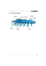
Page 15: ...13 2 3 Position of the stickers ...

Page 16: ...d in the top position to ensure a good entry In working position the top link must be fitted so that it raises towards the implement Incorrect Correct 3 2 Working depth of the tines The working depth will be adjusted by means of the pins S1 and S2 of the pin adjuster V1 Range of working depth 5 cm to 30 cm 3 3 Reconsolidation effect The reconsolidation effect of the rollers W0 will be adjusted via...

Page 17: ...scs The hollow discs K3 must be adjusted in depth by means of the pin adjuster V4 so that they level the dams which were made by the tines H0 of the rear row 3 6 Outer discs The working depth of the outer discs R0 must be adjusted a little shallower than the hollow discs K3 and that by means of the pin adjuster V4 ...

Page 18: ...cs 4 3 Check chains or sway blocks It is essential that the check chains or sway blocks are adjusted so that the lower links are free to move sideways when in working position 4 4 Tractor hydraulics During work the tractor hydraulics must be set to floating position or mixed control 4 5 Required power sources and sockets For the electric use of the implement the following power sources must be ava...

Page 19: ...always be loaded with 20 of the tractor dead weight at minimum How to calculate the minimum front ballast and the increasing of the rear axle load is described in detail as follows GV Weigth of front ballast front implement TV Front axle load of the tractor without mounted implement TL Tractor dead weight TH Rear axle load of the tractor without mounted implement GH Weight of the implement combina...

Page 20: ...rear axle load requires that all above mentioned measurements and weights are known If they are unknown and cannot be found out there will be only one way to avoid overloads Please weigh your tractor with mounted and lifted implement to find out the actual rear axle loading and front axle unloading and that in compa rison with the axle loads of the tractor without implement b a b T b T d c G G L V...

Page 21: ...nkage of the tractor must be adapted or the dra wbar A0 and if required the top link pin must be replaced by a cor resonding version The maximum allowered tractor po wer and measurements accoring to to ISO 730 1 can be learned from the following table kW HP Cat Diameter of the pi vot of the drawbar mm Length of the drawbar mm collar dis tance Distance of the tractor lo wer links mm Distance betwee...

Page 22: ...llers The lower position should be cho sen when the roller will be loaded with too much pressure and cloggs due to the high pressure load 5 4 Re positioning the drawbar It it is required to change the height position of the drawbar the bolts A5 must be loosened the drawbar plates A4 with drawbar turned by 180 and then fitted again The nuts of the bolts must be tightened with a torque of 580 Nm and...

Page 23: ...e Connect top link so that the con nection point atthe implement is higher than that of the tractor also during work Secure top link pin A1 by means of securing pin Fit lighting equipment with war ning boards when driving on pu blic roads Connect electric cables Connect hydraulic pipes For work the lighting equipment with warning boards must be detached in or der to avoid damages ...

Page 24: ... to position control Lower implement and remove top link from the implement Remove lower link from the drawbar A0 Disconnect electric cables Disconnect hydraulic pipes and put them into the holder A9 Read and adhere to the General Safety Instructions as well as to the Instructions Attached Implements ...

Page 25: ...ded in as follows Before folding in lift the implement completely By means of setting the spool valve to folding position 1st pressure po sition the lateral sections will be folded in until their end stops Now the folding device K2 locks automatically Check whether the hooks K3 and K4 of the folding device are locked correctly and whether the hydraulic ram K5 is opened completely Lock tractor spoo...

Page 26: ...lock tractor spool valve and set it into the 1st pressure positi on folding in position and af terwards into the 2nd pressure position folding out position The lateral sections will be unlo cked automatically via the hy draulic ram K5 and folded out now Read and adhere to the General Safety Instructions as well as the Instructions Hydraulic Assembly Never fold in and out the lateral sections when ...

Page 27: ...ill be adjusted with raised cultivator If with raised cultivator the rollers are still touching the ground or are too close to the ground then with fully lowered cultivator the pins S2 must be placed in a lower hole above the carrier S3 8 2 Tine position The tine position respectively the shares of the implement can be al tered A flat share position redu ces the traction requirement a steep share ...

Page 28: ...ide These points will be bolted to the sahre foot 10 S Alternatively also change wing shares are available with points S12P and wing shares FL23D RH and LH which will be bolted to the foot 10 S FL This foot is provided with additonal holders for the wing shares If it is required to work deep it will be recommended to use share poitns S8 P with foot 10 S if it is required to work over the complete ...

Page 29: ...iscs 8 5 1 General Instructions The outer discs R0 will be bolted to the ends of the hollow disc carriers via its frame tube They should not work so deep as the inner hollow discs K3 their purpose is only to move the soil which has been thrown beyond the working width into the grooves left by the outer tines Af ter having loosened the clamping bolts R1 the outer discs can be moved laterally so tha...

Page 30: ...vents a swinging back of the straw harrow in lifted po sition For work the straw harrow must be adjusted so that the straw will be distri buted very well but not pile up It must be ensured that the tines P1 of the straw harrow do not touch the rollers The steeper the harrow tines P1 are positioned the better is the crumbling The less steep the harrow tines P1 are positioned the less is the risk of...

Page 31: ...ded by means of the ec centric lever J1 Therefore the eccentric lever will be fitted to one of the holes J3 of the wheel stalk J4 directly above the bracket J5 secured and pressed down WARNING The weel stalk J4 must always be held by the eccentric lever J1 or the pin J2 Never dismount eccentric lever and pin at the same time After each depth adjustment the pin J2 must be secured again Read and adh...

Page 32: ...bolt into hole concerned and tighten carefully Only shearbolts according to the schedule below should be used Otherwise there is a serious risk of damage to frame tine or disc carrier or a premature failure may be experienced Read and adhere to the General Safety Instructions as well as to the Instructions Maintenance When changing shearbolts use suitable tools only Tines Disc carrier with shearbo...

Page 33: ...ds when touching an obstacle and automatically return to the wor king position once the obstacle has been passed The cultivator is additionally pro tected by means of shearbolts H1 As option also the pairs of hollow discs K3 and the outer discs R0 are available with automatic overload safety device Read and adhere to the General Safety Instructions Coil springs are under load The tines trip to the...

Page 34: ... 500 trapeze disc roller TSW 500 knife roller MSW 600 and rubber ring roller GRW 590 The tube bar rollers double rollers and trapeze ring roller are maintenence free The trapeze packer roller trapeze disc roller packer roller and rubber ring roller are equipped with adjustable scrapers which must be re adjusted from time to time The knife roller is equipped with a bar with knifes as scrapers which...

Page 35: ...packer roller can be adjusted by means of a 19 mm spanner the eccentric nuts W6 will be adjusted by a 24 mm span ner Before adjusting the eccentric nut the corresponding screw W7 will be loo sened by means of a 19 mm spanner and after adjustment tightened again The scrapers of the rubber ring rollers are provided with slotted holes which enable a re adjustment ...

Page 36: ...e valid for all packer rollers trapeze pak ker rollers and trapeze disc rollers Each scraper of the rubber ring roller must be adjusted so that it is positioned in a distance of 8 to 12 mm to the rubber rings Heat treated scrapers Synthetic scrapers fitted to the roller surface W5 with a little pre tension Hard faced scrapers or scrapers with hard metal plates ...

Page 37: ... clockwise so that they are unloaded 11 4 2 Giving way of the knifes The giving way of the knifes M1 to the top is limited by the pin M6 If requi red a low making way to the top is admitted 11 4 3 Adjustment of the knife frame When the range of adjustments by means of the pin M2 is insufficient the knife frame M7 can be positioned higher in relation to the carrier arms The refore the bolts must be...

Page 38: ... the position of the top link Therewith the tractor hydraulics must be set to floa ting position or mixed control Steep positioned top link low reconsolidaton effect Not so steep positioned top link medium reconsolidation effect Flat positioned top link high reconsolidation effect WARNING If the top link is positioned too steep the entry behaviour of the cutivator will be reduced to the minimum Re...

Page 39: ...ry 100 hours of use before the winter break after the winter break Pivots of the overload safety units 2x x x x Hollow discs 1x x x Greasing all pins x Greasing all shiny areas of the hollow discs outer discs and guide boards x Hydraulic rams x x x Folding pivots x x x ...

Page 40: ...red with Loctite 12 3 Wearing parts Worn hollow discs outer discs a s o must be replaced in time so that the car rying parts will not be damaged or worn IMPORTANT Do not clean this implement with a Pressure Washer during the first 6 weeks After this time a minimum nozzle distance of 60 cm must be observed with a maximum 100 bar and 50 C temperature Read and adhere to the General Safety Instruction...

Page 41: ...ards with lighting equipment are available The warning boards with lighting equipment must be detached before work so that they cannot be damaged With shallow working depth adjustment the foldable implement is wider than 3 m Therefore the maximum working depth must be adjusted before driving on public roads The regulations and laws concerned must be abided by ...

Page 42: ... up to KW PS 140 190 140 190 170 230 170 230 Min working depth 5 cm 5 cm 5 cm 5 cm Max working depth 30 cm 30 cm 30 cm 30 cm Thorit 9 500 K 9 500 KÜ 9 600 K 9 600 KÜ Weight apprx 2781 kg 3481 kg 3191 kg 4023 kg Length apprx 415 cm 445 cm 415 cm 445 cm Transport height 300 cm 300 cm 300 cm 300 cm Tranpheight apprx 350 cm 350 cm 400 cm 400 cm Working width 500 cm 500 cm 600 cm 600 cm Centre of gravi...

Page 43: ...41 15 MAIN WEARING PARTS ...

Page 44: ...05 9885 Spring ring 12 DIN127 7 337 4386 Point S8P 80x12x230 8 337 4391 Point S12PK 120x12x200 9 337 4392 Point S12P 120x12x230 10 337 4395 Guideboard LB1 100x8x305 11 337 4398 Outer guideboard LBR2 RE 12 337 4399 Outer guideboard LBR2 LI 13 337 4428 Wing share FL23D GEK RE 14 337 4429 Wing share FL23D GEK LI 15 337 4401 Guideboard LB3 80x8x305 16 465 3680 Tine 70x22x875 17 465 3681 Tine 70x22x795...

Page 45: ...nt it must be disposed of environment friendly by a specialist 19 NOTES As the version of equipment is depending from the order the equipment of your implement and its description concerned may deviate in some cases To ensure a continuously updating of the technical features we reserve the right to modify the design equipment and technique ...

Page 46: ...44 ...

Page 47: ...wbar 14 19 20 F folding 23 H hollow discs 15 hydraulics 16 K knife roller 35 KW PS 40 L length 40 load 18 lower link 14 M maintenance 37 minimum axle load 18 minimum front ballast 18 O outer discs 15 27 overload safety device 31 P pairs of hollow discs 27 power sources 16 ...

Page 48: ...46 S scraper 33 34 shearbolt 30 shearbolt device 30 sockets 16 straw harrow 28 T technical data 40 three point linkage 19 top link 14 transport height 40 W weight 40 working depth 14 ...

Page 49: ..._________________________________________________________________________________________________________________________________________________________________________________________________________________________________________________ Make model maerke type marca tipo No to which this certificate applies conforms to the basic safety and health re quirements of EEC Directions 89 392 som denn...

Reviews: