
19
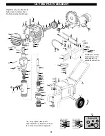
MAINTENANCE & SERVICE (DC-4000)
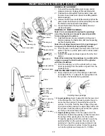
REMOVAL AND CLEANING OF FOOTVALVE:
1)
Turn unit off, ensure that prime valve is open, and all
pressure is relieved. Unplug unit from electrical outlet.
2)
Tilt unit back on handle.
3)
Using a large crescent wrench, unscrew footvalve com-
plete with suction tube. The seal for the footvalve is part of
the pump cylinder and cannot fall out.
4)
Remove retaining clip and ball.
5)
While footvalve is removed, you can look up inside pump
to see hole in center of shaft where shaft ball is.
6)
If hole is obstructed or plugged, use a small screwdriver (or
piece of wire) and compressed air to free up ball. Be sure
to cover end of return line with a rag so paint/solvent in
pump is not blown into your face!
7)
Should this not be sufficient, see steps 1-12, 16 and 17 of
the DC-4000 packing instructions. Once o.k. proceed to
next step.
8)
Clean all parts including intake screen and pipe.
9)
If ball is very pitted or scored, it must be replaced. Inspect
seat inside of footvalve body. If it is damaged the footvalve
housing must be replaced.
10) Lightly oil ball and put into footvalve housing. Replace
retaining clip.
11) Lubricate nose and threads of footvalve with grease.
Thread into unit and tighten 15-20 ft/lb. Unit is now ready to
test in solvent etc.
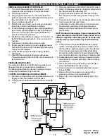
PRESSURE CONTROL BOX:
The pressure control box for the DC-4000 is a precision unit,
designed to require no regular service or adjustment.
The following instructions are intended to guide you through
removal and re-installation of the control box.
CONTROL BOX REMOVAL AND REPLACEMENT:
1)
Shut down unit, open prime valve to release pressure, and
trigger gun to be sure pressure is out of system.
2)
Unplug cord from electrical outlet and wrap around handle
of unit.
3)
Disconnect paint hose, inlet and return hoses from sensor.
4)
Using 3mm allen key, remove 4 x bolts from behind control
box. Box will come free with about 6-8".
5)
There are four wires to disconnect. Disconnect the two
from the power cord (the lower pair) first. These go to the
switch.
6)
The second pair of wires go the the bridge rectifier from the
motor (upper pair). Disconnect these.
7)
Control box is now free from pump and can be serviced.
Should service extend beyond changing of switch or
breaker, control box should be sent to nearest Lemmer
service center.
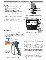
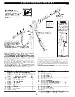
NOTE: Electrical shock warning. Some components of the
control box operate at full 120 volt 15 amp current. Do not
attempt to adjust the control box yourself. Excessive and
unsafe pressures may be attained by unauthorized tam-
pering.
8)
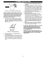
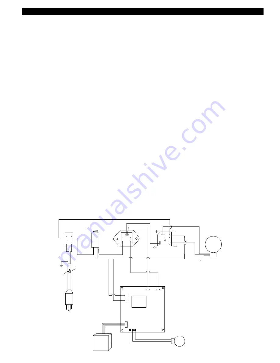
Connect motor wires (upper black/white pair) to bridge
rectifier. The black goes to the positive (notched corner)
and the white to negative (opposite corner). See diagram.
9)
Connect power wires (lower pair of black/white). Black
connects to terminal of switch in line with breaker. White
wire connects to terminal in line with wire to bridge rectifier.
10) Double check all connections. Mixup of power and motor
wires will result in complete destruction of triac and bridge
as a minimum.
11) Lift box into place, while gently tucking in extra length of
wires. Install and tighten the allen screws.
12) Connect return line, and paint inlet/outlet lines to sensor.
Torque 20 ft/lbs.
13) Place suction in solvent, open prime valve and turn
pressure to minimum. Ensure switch is OFF.
14) Plug in unit. Turn on and check for indicator light. Prime
and test.
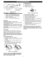
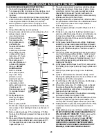
on/off
switch
white
black
circuit
breaker
triac
bridge
black
white
motor
purple
blue
circuit
board
J8
J7
J1
J2
orange
yellow
sensor
potentiometer
(pressure control)
IMPORTANT:
the motor wire polarity
determines direction of
rotation. The wires must be
connected as shown to
result in a clockwise
rotation as viewed from the
fan cover.
CAUTION:
connect the purple
and blue wires (J7 & J8)
exactly as shown. Incorrect
connection will result in
erratic motor operation, or
no operation at all.
CAUTION:
connect the orange
and yellow wires (J1 & J2)
exactly as shown. Incorrect
connection will result in
erratic motor operation, or
no operation at all.
Figure 16. Wiring
diagram, DC-4000


