20
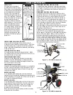
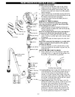
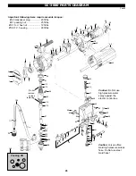
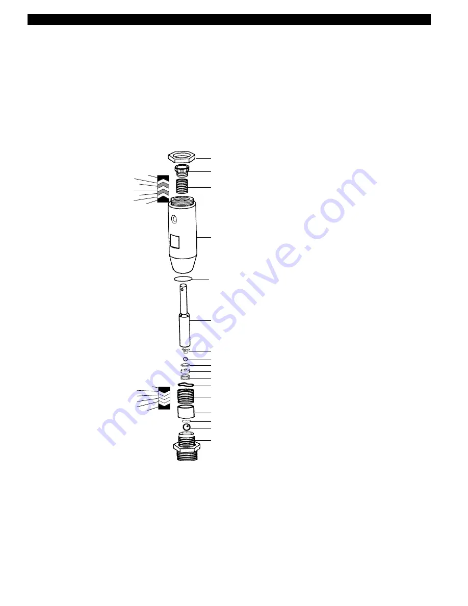
upper packings:
male support
poly
leather
poly
leather
poly
female support
MAINTENANCE & SERVICE (DC-4000)
DC-4000 PACKING (L050-625 KIT) INSTRUCTIONS:
1.
Flush unit thorougly with appropriate solvent.
2.
Turn pressure control to minimum so that unit stops. Look
in opening of central body to observe position of connect-
ing screw.
3.
If necessary, turn control to prime and down again (briefly)
so that motor runs in short bursts. When motor stops with
connecting bolt at bottom of its travel, turn unit OFF.
4.
Relieve pressure via prime valve, and unplug unit from
electric outlet. Tilt unit back on handle and allow solvent to
drain.
5.
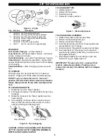
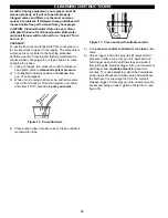
Using a 5mm allen key, remove pail hook.
6.
Using the same wrench, remove connecting screw from
plunger. (newer models
use a 4mm allen key).
7.
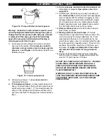
Disconnect fluid hose
from pump section.
8.
Using a pipe wrench,
and holding the
footvalve with another
wrench, remove
suction pipe and screw.
9.
Using a large crescent
or pipe wrench, loosen
locknut pos. # 1. Pump
will unscrew by hand.
10. Place pump assy in
vice, using flat areas on
cylinder, with footvalve
facing up.
DO NOT
OVERTIGHTEN!
Remove footvalve.
11. Place pump opposite
way in vice. Using
pliers etc, remove
packing nut pos. # 2.
12. While holding hand
under pump to catch
piston, gently tap on top
of piston pos. #6.
Packing spacer, pos. #
14 may also fall out at
this time.
13. Gently, using screw-
driver, pry out upper
packings and spacers
pos. # 3.
14. Remove pump cylinder
#4 from vice. Using fingers (or screwdriver and due care)
remove spacer, lower packings and wave washer pos. #
14, 13, 12.
15. Remove retaining clip pos. # 15, and ball pos. # 16 from
footvalve body. Ball seat is pressed into housing and is not
replacable.
16. Place wrench flats of tip of piston in vice, and using 10mm
allen wrench, take out shaft valve nut and seat pos.# 11,
10. Take piston from vice and remove shaft ball and
copper seal pos. 8, 9.
17. Thoroughly clean and dry all parts (except old packings).
18. Inspect upper and lower chrome areas of piston. Some
scratching is normal. If very extreme scratches or areas
missing hard chrome exist, the piston will have to be
replaced. A distinct darker, duller color in some areas may
indicate wear through the hard chrome.
19. Although new balls are supplied with kit, old ball condition
is a good indicator of seat wear. If the old balls are chewed
up or visibly smaller, take care to inspect shaft and
footvalve seats for wear.
20. Place new upper packings in oil (L034-125) to soak for 5-
10 minutes.
21. Put piston in vice using flats. Install new ball and copper
seal. Use a little bit of grease to hold seat in shaft valve nut.
Put one or two drops of blue or red locktite on threads.
Install by hand into shaft, then use wrench to tighten 40-45
ft/lb. Remove from vice.
22. Lightly grease inside of lower pump cylinder. Install wave
washer(s) and male packing spacer with flat end towards
washer. Lightly grease each packing and install with lips as
per diagram. Install female space V end first and push in
tightly by hand.
23. Turn pump cylinder over and lightly grease upper packing
bore. Install metal spacerflat end down. Install 1 x plastic
packing V end first, then in turn 1 x leather, 1 x plastic, 1 x
leather, 1 x plastic. Now put in thick plastic spacer V end
down. Lightly grease packing nut inside and on threads.
Install gently hand tight.
24. Lightly grease piston surfaces. Insert 10 mm allen wrench
for a holding tool, and push piston up through cylinder until
it stops.
25. Place pump cylinder open end up in vice. Install brass
spacer.
26. Lightly oil new footvalve ball, and place in body. Install
retaining clip. Lightly grease nose of valve and threads and
install approx. 20 ft./lb in pump cylinder.
27. Use teflon tape on threads of suction pipe. Hold footvalve
with wrench and install tube 10-15 ft/lbs.
28. Ensure large locknut pos. # 1 is bottomed out on threads.
Now grease threads of pump cylinder. Thread cylinder
assy. into central body until pin hole in top of piston just
lines up with pin hole in plunger.
29. Place one or two drops red or blue locktite on connecting
pin threads. Install pin and tighten 10 ft/lb.
30. Thread pump assembly onto unit until it bottoms out. Now
back pump up just enough that the paint outlet is in the
correct position. Securely tighten the locknut. (60-70 ft/lb)
31. Install paint hose to pump assembly, tighten 20 ft/lb. Place
a container of solvent under pump intake and set unit
upright.
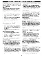
32. Gently tighten packing nut until there is a slight resistance.
DO NOT OVERTIGHTEN OR PACKING/PISTON LIFE
WILL BE GREATLY REDUCED. Tighten just enough to
prevent leakage. Lubricate with L034-120/125 oil.
33. Prime and pressure unit checking for leaks.
DO NOT
TIGHTEN PACKINGS WITH UNIT RUNNING. FIN-
GERS OR TOOLS CAN BE TRAPPED BETWEEN
PACKING NUT AND PLUNGER, RISKING LOSS OF
fFINGER(S) OR SEVERE PERSONAL INJURY.
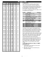
1
2
3
4
6
7
8
9
10
11
12
17
14
16
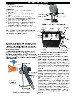
lower packings:
male support
teflon
teflon
teflon
teflon
female support
○
○
○
○
○
○
○
○
5
13
15

