background image

25

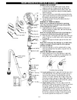
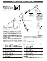
L-65 SPRAY GUN OVERHAUL

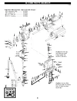
Use diagram on opposite side for reference.
Tools needed:

10 mm socket and driver
2 x 8" or larger crescent wrench
1 x L-65 repair kit
Cleaning brush and lacquer thinner
needle nose pliers

1) Initiate shut down procedure:

Shut Down ProcedureAlways follow Shut Down
Procedure before starting any troubleshooting,
servicing or cleaning.
a) Engage the trigger safety lock in the locked posi-

tion. Test the trigger safety lock to ensure the lock
is working properly.

b) Turn pressure regulator to minimum.
c) Disconnect electric plug from wall socket, or

disconnect air supply.

d) Open the dump valve to relieve pressure. Leave

open until ready to spray or test or clean.

e) Remove the spray tip.
f) Disengage the trigger safety lock.
g) Trigger the gun into a metal pail to relieve any

remaining pressure. A metal part of the spray gun
should be held firmly against the grounded metal
pail when relieving the pressure from the gun. (A
grounded metal pail is not required for non-
flammables such as latex.)

h) Reset the trigger safety lock to locked position.

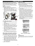
2) Using the two crescent wrenches, disconnect the gun

and gun handle from spray hose.

3) Remove spray  tip or attachment assembly from gun.
4) Hold gun trigger open and remove seat (#4) from

gun. Release trigger.  Never remove or attach seat
unless trigger is held in the open position.  Per-
manent and expensive damage to both ball and
seat will result!

5) Using 10mm socket and driver, remove adjusting nut

(#18) from rear of gun.

6) Grasp retainer cap (#17) and pull away from rear of

gun. Remove the two trigger pins (#9) from gun.

7) The ball spring assembly can be removed from the

rear of the gun body by unthreading six to eight turns
and then pulling firmly towards rear of gun body
(#13). Push packing & wedge (#11&12) out of rear of
gun body.

8) Remove gun handle from gun and remove filter and

filter spring.

9) Using points of needle nose pliers, unscrew housing

nut (#16) from housing (#13). Grasp end of shaft
(#14) and remove. Take spring (#15) off of shaft for
cleaning.

10) If the ball (#10) has a groove worn in it, the ball with

shaft will have to be replaced. Usually the seat will
have to be replaced as well, as it wears against the
ball. Both of these parts are included in the repair kit.

11) Lightly grease wedge & packing & assemble together.

Install wedge first, and then the packing into gun body
until they bottom.

12) Lightly grease spring & outside of housing. Install

spring on spring shaft, and put into housing. Install
housing nut & tighten until flush with rear face of
housing.

13) Thread housing into rear of gun body. Tighten to a

maximum of 3-5 ft/lbs.

14) Examine the trigger pins for wear and equal length.

Lightly grease and install.

15) Install retainer cap on rear of gun and install locking

nut. Tighten locking nut until approximately two
threads show out rear of the nut.

16) Thread gun handle into gun body and hand tighten.
17) Lightly grease threads of seat. Install trigger guard

over open end of seat. Hold gun trigger in open
position and install seat. Tighten to 30-40 ft. lbs. and
release trigger.

18) The retainer cap should have a bit of slack in it and

should not be bottomed against the gun tightly. The
trigger should have 3/8" slack at the bottom of the
trigger before engaging against the trigger pins.

This slack is very important for the correct opera-

tion of your gun.  The gun and safety lock will not
work properly if this step is not performed correctly.

To increase slack, loosen the locknut a little and

test slack again.

To decrease slack, tighten the locknut a little and

test slack again.

With too much slack, the gun may not turn on, but

the safety lock will work fine. With too little or no
slack, the gun may be permanently ON and the safety
lock does nothing.
DO NOT RUSH OR IGNORE THIS STEP, COR-
RECT OPERATION OF THE SAFETY TRIGGER
LOCK REQUIRES PROPER ADJUSTMENT OF
TRIGGER SLACK.

19) Install tip attachment onto gun. Remove gun handle,

install spring and filter, lightly grease threads and re-
install.

20) Place trigger in LOCK position. Install gun to hose,

tightening securely. Install tip where applicable. The
gun is now ready for testing and use.

HIGH PRESSURE!

INJECTION HAZARD!

Summary of Contents for DC-3000

Page 1: ...materials sprayer must be placed at least 20 feet from target in a well ventilated area Vapours can be ignited by static discharge or electrical sparks and result in severe personal injury LEMMER airl...

Page 2: ...HINTS FOR AIRLESS SPRAYING PAINTING AND TIP SELECTION 12 SPRAY PAINTING METHOD 12 HELPFUL HINTS FOR TROUBLE FREE PAINTING SPRAYER 12 PAINT 12 SPRAY TIPS 12 FILTERS 12 PAINT HOSE 12 ELECTRICAL 13 EXTEN...

Page 3: ...garde Ne jamais mettre la main les doigts ou toutes parties du corps contre la buse Le port de gants et de v tements n est pas n cessairement une forme de protection non plus Laisser le cran de suret...

Page 4: ...to move equipment DO NOT kink or bend the hose sharply 17 Keep children or anyone not familiar with airless spray systems away from equipment and work area 18 Conductive metal containers must be used...

Page 5: ...tor operates only as fast as the job requires again reducing wear DC 4000 only Accurate spray pattern with minimal overspray Minimal or no thinning of paint products Pumps straight out of original pai...

Page 6: ...ds depending on how much voltage it is sent by pressure control box This allows for highly accurate control of pressure Motor also features long life brushes which are readily accessible from the outs...

Page 7: ...t ELECTRONIC CONTROLS DC 4000 OFF The first 10 20 degrees of pressure knob rotation do not activate unit PRIME ZONE The next approx 20 degrees of rotation will turn the motor on at a constant slow spe...

Page 8: ...94 029 8 40 DEG 3 1 429 L043 295 029 10 50 DEG 3 1 529 L043 296 029 12 60 DEG 3 1 629 L043 297 029 14 70 DEG 3 1 729 L043 298 029 16 80 DEG 3 1 829 L043 299 029 18 90 DEG 3 1 929 L043 313 031 6 30 DEG...

Page 9: ...protect against accidental injection and prevents tip from slipping out of position Patented Diffuser safer unclogging in clean out posi tion TO OPERATE When tip clogs turn zip tip handle 180 to clean...

Page 10: ...of fan width 8 1 foot 15 orifice size in thousands of an inch 015 Y Yellow 100 mesh filter R Red 180 mesh Y Yellow 100 mesh W White 50 mesh not recommended Tip volume at various pressures Gallons per...

Page 11: ...up pressure about 1 6 turn This gives a good low pressure for flushing and cleaning 8 Aim gun into empty metal pail holding gun body against pail edge to ground gun for safety Open trigger and allow...

Page 12: ...at gives an adequate spray pattern is the best pressure to use It will give maximum pump and tip life and produce minimum overspray 2 Typically thicker materials require larger tips and higher pressur...

Page 13: ...the gun first HELPFUL HINTS FOR TROUBLE FREE PAINTING PAINT HOSE 1 INSPECT THE HOSE PERIODICALLY DO NOT USE KINKED WORN OR DAMAGED HOSE SEE WARNINGS ON PAGES 3 4 2 Use only hose that is designed for...

Page 14: ...n causes of problems If followed these guidelines will insure trouble free performance from your sprayer CAUTION Clean with water if latex is used Clean with paint thinners for oil based paints Both w...

Page 15: ...gun filter Remove filter and brush clean with appropriate solvent Inspect filter for pinholes plugging or other damage Replace if required Re install with double lip end pointing up into gun Lightly...

Page 16: ...ld brushes put back on same side of motor same way up as before to reduce break in time 6 Install brush caps DO NOT OVERTIGHTEN AS BRUSH CAPS ARE BAKELITE AND WILL BREAK 7 Put unit in solvent open pri...

Page 17: ...Push the packings out of the cylinder with a screw driver by pushing from the inside out push from the opposite end INSTALLING NEW PUMP PACKINGS 9 Apply a light coat of oil to the packings Install bot...

Page 18: ...the fluid section into the main pump housing Rotate the fluid pump to align the hole in the piston shaft with the holes in the yoke 25 Insert the pin through the yoke and piston Snap the retaining cl...

Page 19: ...disconnect Disconnect the two from the power cord the lower pair first These go to the switch 6 The second pair of wires go the the bridge rectifier from the motor upper pair Disconnect these 7 Contr...

Page 20: ...and footvalve seats for wear 20 Place new upper packings in oil L034 125 to soak for 5 10 minutes 21 Put piston in vice using flats Install new ball and copper seal Use a little bit of grease to hold...

Page 21: ...Sprayer starts up but does not draw up paint III Sprayer will not maintain pressure or has low output IV Upper end of fluid section leaks V Poor spray pattern VI Spray gun won t shut off VII Spray ti...

Page 22: ...APHRAGM These sprayers are the same as the electric diaphragm pumps but with the advantage of a gas engine All use Honda motors and belt drive systems AUTOMATIC GUNS Suitable for all heavy duty airles...

Page 23: ...ls L034 222 Extra large overalls L034 223 1 Gal stir rod 2 3 8 dia 3 8 chuck L034 050 1 Gal stir rod 3 1 4 dia 3 8 chuck L034 051 5 Gal stir rod 4 3 4 dia 1 2 chuck L034 052 SPRAY HOODS Spray hoods pa...

Page 24: ...to change spray tip or leave the unit unattended without first shutting off pump releasing fluid pressure and locking the trigger safety lock Conductive metal containers must be used when flushing fl...

Page 25: ...ke spring 15 off of shaft for cleaning 10 If the ball 10 has a groove worn in it the ball with shaft will have to be replaced Usually the seat will have to be replaced as well as it wears against the...

Page 26: ...2 112 94 112 56 112 97 98 99 100 101 102 103 104 105 106 107 108 109 110 Do not remove unless replacing Important following items require accurate torques 62 transducer plug 20 ft lbs 91 packing nut 2...

Page 27: ...540 Screw 4 54 L045 541 Electric cord 1 55 L045 542 Strain relief 90 1 56 L036 001 Connector 1 4 m 2 57 L045 543 Fuse holder 1 58 L045 544 Fuse 10 amp 1 59 L050 617 18 connection hose 1 60 L036 091 El...

Page 28: ...packings female support poly leather poly leather poly male support lower packings male support poly poly poly poly female support Caution only use fibre braid high pressure airless hose Do Not use st...

Page 29: ...allen 5 42 L050 519 Oil seal 1 43 L050 526 Rod bearing 1 44 L050 532 Rod bushing 1 45 L050 530 Connecting rod incl Pos 44 1 46 L050 524 Cover screw M4 x 10 3 47 L050 523 Front cover 1 48 L050 537 Pai...

Page 30: ...poly poly poly poly female support male support 64 Only replace this seal if external leak is evident Once seal is removed it must be replaced 84 92 80 81 93 88 89 90 91 86 77 78 83 82 87 66 65 75 74...

Page 31: ...Strain relief 14 3 thick panel 1 35 L050 535 Drain plug 1 36 L001 555 Copper seal 3 40 L001 550 Washer knurled lock M10 5 41 L050 520 Housing bolt M10 x 1 5 x 16 allen 5 42 L050 519 Oil seal 1 43 L050...

Page 32: ...rtation costs and other incidental direct special or consequential damages or loss specifications are subject to change without notice May 00 caract ristiques sont sujets changement sans pr vis Mai 00...

Reviews: