

9
TO CHANGE ZIP TIPS:
1) Rotate zip-tip 90˚.
2) Remove from housing.
3) Install new zip tip.
4) Rotate 90˚ to spray position.
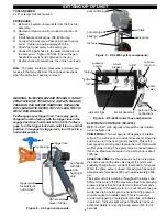
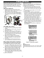
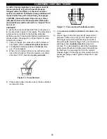
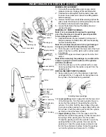
Figure 7. - Removing tip seal.
TO CHANGE SEAL ASSEMBLY:
1) Relieve line pressure and set gun safety.
2) Remove zip tip housing from gun.
3) Remove zip tip from housing.
4) Insert zip tip cylinder into front of housing and press
seal assembly out of housing.
5) Install zip tip (4) through slot in guard and into body.
6) Insert seal ass'y (2) through gun nut to seat seal
around zip tip cylinder (press firmly to insure seal is
tight against cylinder).
7) Insert tip/gun washer (3) over spring (in gun nut).
Install unit on gun. Tighten gun nut.
IMPORTANT: The seal ass'y (2) is a wear part that
must be replaced periodically. If leaking occurs,
replace the seal ass'y immediately before it damages
the tip (4).
ZIP TIP INFORMATION
FEATURES:
Fast Tip Size Changes - no tools required.
Long Seal Life - withstands harsh solvents - won't swell
or leak - replaces in minutes.
Tip Rotates Easily - even under “high pressure” clog-up.
Venturi-Guard - less paint accumulation - helps protect
against accidental injection and prevents tip from slipping
out of position.
Patented Diffuser - safer unclogging in clean-out posi-
tion.
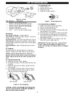
TO OPERATE:
When tip clogs, turn zip-tip handle 180˚ to "cleanout
position". Trigger gun and line pressure will purge clog.
DO NOT spray or empty the hose in "clean out"
position, this will cause extreme wear and premature
failure. Always remove the tip when cleaning out the
hose.
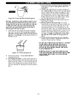
TO CLEAN PLUGGED TIP:
1) Rotate the tip to the “Clean” position.
2) Pull trigger and spray. This should clear the tip of any
blockage.
3) Rotate the tip back to the “Spray” position and con-
tinue spraying.
4) If the clogging continues, clean or replace the gun
filter and see the section in this manual on instruc-
tions for straining and thinning paint.
Clean Position Spray Position
Figure 6. - Tip unclogging.
CAUTION: DO NOT USE A NEEDLE OR SHARP OB-
JECT TO CLEAN THE TIP. TUNGSTEN CARBIDE IS
BRITTLE AND CAN BE CHIPPED.
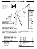
3
2
1
4
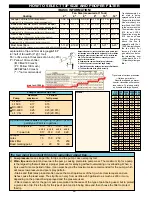
Figure 5. - Zip tip
Pos. Part nos. Description
1
L043-001 Zip Tip housing with guard
L043-007 Zip Tip guard (not shown separately)
2
L043-005 Zip Tip seal kit (includes gasket #3)
L043-006 Spring, 3/pkg (not shown separately)
3
L043-008 Nylon gasket
L043-009 Tube of 8x nylon gaskets
4
L043-***
Zip Tip - see chart on opposite page