10
INSTALLATION
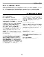
CHECK OUT AND START UP
NOTES AND GENERAL ELECTRICAL
The Lennovator Control Module is rain proof and does not
have to be protected by a weather-tight enclosure.
Install the equipment to permit safe access for servicing and
routine maintenance of the Lennovator Control Module.
All electrical connections to the Lennovator Control Module
must be accomplished by a qualified electrician in
accordance with the National Electrical Code or the
Canadian Electric Code and in accordance with any local
electrical codes in effect at the time of installation.
All electrical connections must be made in accordance with
the wiring information contained in this manual, or on the
back of the field wiring access panel of the Lennovator
Control Module.
WARNING:
Improper electrical connections or conductor
sizing may cause the Lennovator Control Module to operate
improperly, create the potential for electrical hazard, and
may void the warranty.
The electrical supply for permanently connected Lennovator
Control Modules (hardwired for 120V and 240V operation)
must include a suitably rated switch or circuit breaker to
open all ungrounded supply conductors to comply with
Section 440-52 of the National Electrical Code,
ANSI/NFPA70. The disconnecting means must be within
sight and readily accessible to the user of the equipment.
The electrical supply for permanently connected Lennovator
Control Modules must also include a suitably rated Ground
Fault Circuit Interrupter (GFCI) to comply with Article 680-42
of the National Electrical Code, ANSI/NFPA70.
These installation instructions are provided as guidelines for
use and interpretation by knowledgeable installers. Wire
size, number of circuits, size of circuit breakers, etc. must be
selected for the particular system being installed. Refer to
Appliance Data Label to determine specific electrical
requirements.
CHECK ALL WIRE CONNECTIONS
Check all high voltage terminals for tight/secure connection.
Check all low voltage terminals for tight/secure connection.
Check the grounding wire for proper connection from the
Lennovator to sub-panel and main panel.
CHECK HEATER
Check heater for high limit protection.
Check heater for pressure or flow switch protection.
Check the connections of control terminals to the heater for
proper connection.
CHECK CONTROL PANELS
Make sure the remote control panel is accessible.
CHECK OUT AND START UP
EXTERNAL GAS - FIXED HEATER INTERCONNECT
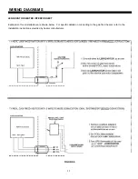
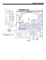
Examples of two typical installations of the Lennovator heat control wired to 2 and 3 wire external gas heaters are shown in
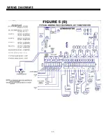
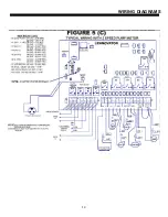
Figure 6. Refer to interconnection Figures 5 (A), 5 (B) and 5 (C).
IN ALL CASES REFER TO INSTALLATION INSTRUCTIONS PROVIDED BY THE HEATER MANUFACTURER.
Summary of Contents for Lennovator
Page 4: ...This Page Left Blank Intentionally ...
Page 13: ...9 INSTALLATION ...
Page 16: ...12 WIRING DIAGRAMS ...
Page 17: ...13 WIRING DIAGRAMS ...
Page 18: ...14 WIRING DIAGRAMS ...


