background image

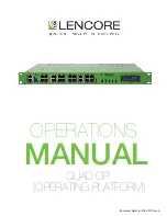
OPERATIONS

MANUAL


QUAD OP

 (

OPERATING PLATFORM

)


Doc

ument 

Number

:


200-0013


R

ev A

Summary of Contents for i.Net Quad OP

Page 1: ...OPERATIONS MANUAL QUAD OP OPERATING PLATFORM Document Number 200 0013 Rev A...

Page 2: ...ION FEATURES CAPABILITIES WIRING HANG SPEAKERS Configuring The System Using The System Final Wiring Checklist table of contents 1 2 In the event of trouble please contact Name Address Phone Number 4 9...

Page 3: ...does not fit into your outlet consult an electrician for replacement of the obsolete outlet 10 Protect the power cord from being walked on or pinched particularly at plugs convenience receptacles and...

Page 4: ...Sound frequencies and contour can be adjusted and set to any point on the acoustical curve from 20 Hz to 20 kHz making i Net the first networked sound masking system to make fine tuning the entire spe...

Page 5: ...nformation Four independent OP s in one unit for a total of 128 speakers on one unit Four IR input ports to control each OP separately with IR wall plates Installing the i Net Quad OP The i Net Quad O...

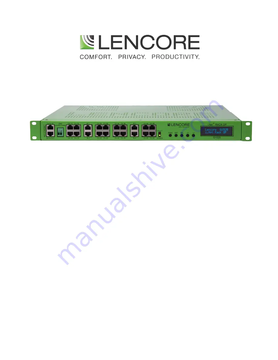
Page 6: ...to these inputs using RJ45 cables 4 Channels Connect external speakers to the Channel s RJ45 connectors 5 LEDs The PWR LED is on when power is applied to the unit The Fault LED is on when the system...

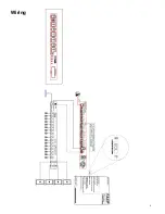
Page 7: ...Wiring 4...

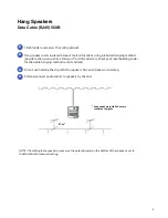
Page 8: ...ta In On the last OP only connect a data terminator to the OP s data out port 2 Wire a ground wire from the GND connector to the previous and next OP ground or to the headend common Audio Common not b...

Page 9: ...Wiring Speaker connections 1 Connect the external speakers to the appropriate channel using cat 5 RJ45 cables Note U refers to unit number not the OP number 6...

Page 10: ...rs and from speaker to speaker The pin out on the RJ45 is 568B The RJ45 connectors for the SPEAKER cables are non shielded 1 5 2 6 3 7 4 8 PINS 568 B ORANGE WHITE ORANGE GREEN WHITE BLUE BLUE WHITE GR...

Page 11: ...n out on the RJ45 is 568B The RJ45 connectors for the SPEAKER cables are non shielded 1 5 2 6 3 7 4 8 PINS 568 B ORANGE WHITE ORANGE GREEN WHITE BLUE BLUE WHITE GREEN BROWN WHITE BROWN 1 2 3 4 5 6 7 8...

Page 12: ...drill and screw check your local building codes for allowable hanging methods and standards Drive a nail holding the clip with the speaker chain and speaker into ceiling Pull and connect audio cables...

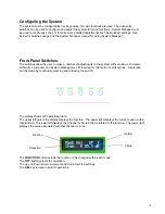
Page 13: ...gh a computer and System Manager are still required for full control of all functions A selection can be made by continually pressing and releasing the switch The display shows OP operational data The...

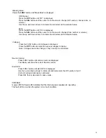
Page 14: ...utton until OP is displayed Press the SEL button until the curser is on the value to change OP number channel letter or volume Use the up and down arrows to increment and decrement the selected value...

Page 15: ...e selected value Voltages Press the FUNC button until Voltages is displayed Press the OPT button to select the various voltages to display Note Voltages cannot be changed they can only be monitored PW...

Page 16: ...internal power supplies are operating When power is first applied the unit will begin a countdown from 20 seconds The display will show the countdown from 20 seconds to 1 second then the status of th...

Page 17: ...shed floor You can make adjustments using the System Manager or hand held remote C For fine tuning Leave all of the ceiling tiles that have an OP hanging above them exposed so that incremental adjustm...

Page 18: ...e large trouble shooting issues at the end of the job TIP Check all speaker wires and speakers for good integrity simply unplug the 1st speaker wire from the OP and connect an RJ45 to a 8 conductor CA...

Page 19: ...lencore com The information contained herein is proprietary to Lencore Acoustics Corp and copyright protected No part of this manual can be copied used or distributed without prior authorization from...

Reviews: