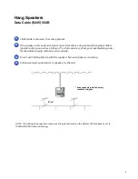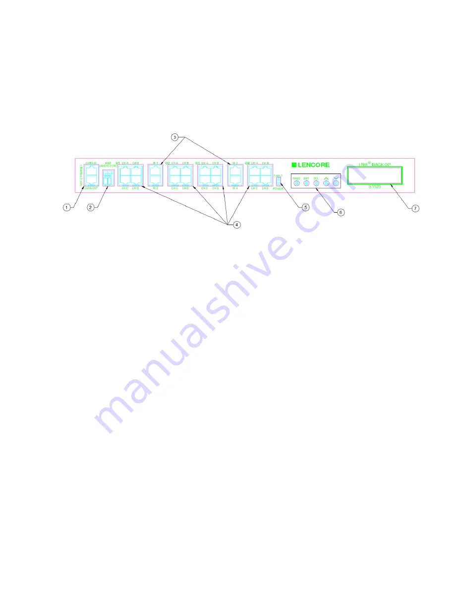
1.
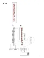
Data In/Out
Connect the Data out from the head-
end or previous OP to the OP Data In.
Connect the Data out to the next OP
Data In using RJ45 cables.
2.
GND
(Audio Common)
Connection for the ground wires to the
head end and next OP ground
connector.
3.
IR
Connect IR
wall
units to these inputs
using
RJ45 cables.
4.
Channels
Connect external speakers to the
Channel
'
s RJ45 connectors.
5.
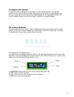
LEDs.
The PWR LED is on when power is
applied to the unit. The Fault LED is on
when the system is in a fault condition.
6. Data Entry
Switches
The
data entry
switches are used to
make a
number of adjustments to the
system
without using a computer.
7.
LCD Display
The LCD displays various diagnostic
messages and configuration
information about the system.
Front Panel
3

