© 2020 Carrier. All Rights Reserved. LenelS2 is a part of Carrier.
2
DOC-6005-EN-US — revision 1.002
Tamper
1.
Connect tamper switch to appropriate inputs of control and indicating
equipment (CIE).
2.
Check that the tamper switch is CLOSED when the lid/cover is closed
and the retaining screw is fitted, OPEN when the retaining screw is
removed and the lid/cover is open. Use fine adjustment screw if
necessary, no more than one turn in either direction, to align indicator
with set point.
3.
Close the lid and fasten with screw supplied. Alternatively fit the
cover in place (the correct orientation is with the cover retaining
feature engaging over the bottom lip of the base) and fasten with the
supplied screws.
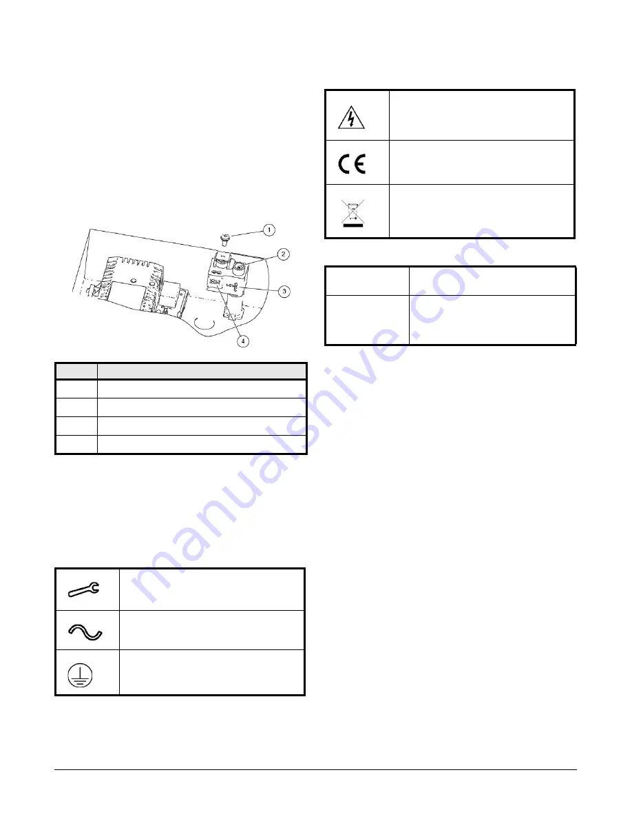
Tamper Arrangement
Operating Instructions
This unit is intended for use by Service Personnel only. There are NO USER
SERVICEABLE parts inside.
The green Mains LED is on while the mains supply is present. In the event
of a fault condition, the red Fault LED flashes and the corresponding (EPS
or GEN) fault signal contacts open.
Maintenance
Note:
Dispose of used batteries according to the battery manufacturer’s
instructions and all local and national regulations.
This unit is intended for use by Service Personnel only. There are NO USER
SERVICEABLE parts inside.
There is no regular maintenance required of the PSU other than periodic
testing, calibration check and replacement of the standby batteries.
Reference should be made to the battery manufacturer's documentation to
determine typical/expected battery life with a view to periodic replacement
of the battery.
Callout
Description
1
Retaining screw
2
Fine adjustment screw
3
Set position indicator
4
Tamper switch connections
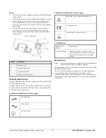
Explanation of Symbols (not all may apply)
Fault Indication
Mains Present
Protective Earth
Shock Risk - Isolate before attempting access
Certification Level
Do not dispose of in unsorted waste
Local Indicators
MAINS LED
(Green)
Mains present
FAULT LED (Red)
Flashes (1s period) when: loss of mains,
battery disconnected, output fuse fail, battery
fuse fail, output short circuit or low output
voltage
Explanation of Symbols (not all may apply)


