• 11 •
Installation, Operation and Maintenance Manual /
ARIA2-IOM-1910-E
WATER COIL ROTATION
WARNING
Fans can reach a speed of 1000 r/min. Do not insert any object
nor hands. During operation, the engine warms up. Allow the
engine to cool before touching it. During the heating operation
the heat exchanger and the connecting pipes can reach high
temperatures (80°C). Wait until the cooling of the exchanger
before touching it or protect hands with suitable gloves. The
water heat exchange coils are suitable to operate in operation up
to the maximum pressure of 8 Bar.
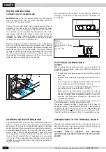
For battery rotation, proceed as follows:
1. Unplug the power to the machine, if connected;
2. Make sure that the heat exchange parts have cooled down
completely, if the unit is installed and powered;
3. Drain any water present inside the heat exchanger, if the
unit is powered;
4. Remove the condensate trap bowl;
3. Remove the battery fi xing screws;
4. Remove the battery taking care not to cut the fi ns and not to
damage them;
5. Remove the knockouts from the opposite side of the unit
(using a screwdriver) to allow the passage of battery fi ttings;
6. Place the battery, turn it upside down without turning it so
that the joints protrude in correspondence of the knockouts
previously removed;
7. Secure the battery with the screws previously removed;
8. It is also recommended to reposition the terminal block
on the opposite side to that of the attacks. If during this
operation, it’s necessary to disconnect the terminal cables,
mark the cable locations to avoid making mistakes in the
process of reconnecting;
9. Replace the condensate drain pan.
CLEANING AND MAINTENANCE
WARNING
Before performing any cleaning or maintenance, disconnect
the device from the power grid!
ORDINARY MAINTENANCE
It is duty of the user to carry out all maintenance operations on
the unit. Only personnel previously trained and qualifi ed may
perform maintenance operations. If the unit must be dismantled,
protect your hands with work gloves.
Monthly checks:
- Make sure the vents are clean. Otherwise, clean them by
suction so as not to damage them.
-
Verify all electrical equipment and in particular the tightness
of the electrical connections
Annual checks:
- Check of all electrical equipment and in particular the
tightening of electrical connections.
-
Check the tightness of all the bolts, nuts and whatever else
can be loosened by the constant vibration of the unit.
- Check that the motor has no traces of dust, dirt and other
impurities. Periodically verify that it works without abnormal
vibrations or sounds, that the entrance to the fan is not
obstructed, resulting in a possible overheating of the
windings.
CLEANING THE AIR FILTER
The device is equipped with air fi lter in the fan inlet.
During normal operation the fi lter withholds impurities present
in the air.
It is necessary to periodically clean the fi lter to maintain the
fi ltration characteristics of the fan air.
You should clean the fi lter at least once a month as follows:
1. Remove the fi lter.
2. Place the fi lter on a fl at, dry surface, remove accumulated
dust with a vacuum cleaner.
3. Wash the fi lter with water and detergent (not solvents).
4. Leave the fi lter to dry in a ventilated place.
5. Replace the fi lter only after ensuring they are perfectly dry.
NOTE: Clean the fi lter at the beginning and end of each
season, or consistent with the work done.
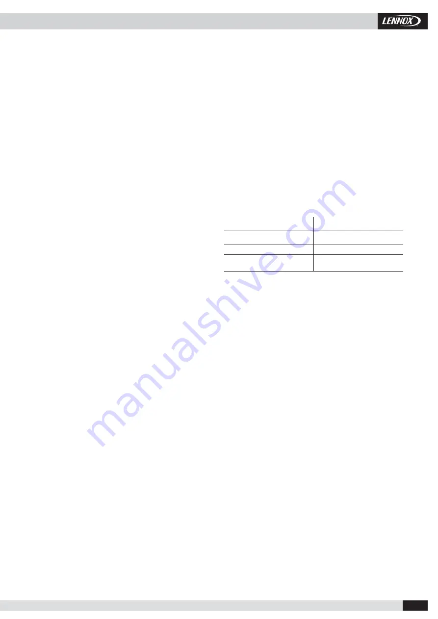
TROUBLESHOOTING
There is little or no output air
Possible cause:
Possible remedy:
incorrect setting of
speed on the control panel
choose the right speed
fi lter clogged
clean fi lter
Ostruction of airfl ow
on discharge or suction
remove the obstruction
The motor does not run? Check that ...
-
the power is on
-
switches or thermostats are in the operating position
-
there are no foreign objects blocking the rotation of the fan
There are no foreign objects blocking the rotation of the fan
- t
he fi lter and battery are clean
-
it is not incoming air in the hydraulic circuit from the special venting
valve
-
the system is correctly balanced
-
the boiler / chiller functions
DISMANTLING DEVICE
This appliance is designed to last for many years. In case of
dismantling, obtain the services of qualifi ed personnel so that the
work is carried out in complete safety.
Always remember that the fi rst operation to be carried out
before dismantling the unit is to unplug it permanently from the
mains. This machine is manufactured using recyclable materials
(copper, aluminum, brass, plastic) assembled by screws and
joints in order to facilitate the unit’s separation.
Contact a fi rm specializing in differentiated waste disposal; just
so you can be sure of proper recycling and contribute to the
environment.


