• 8 •
OU
T
OU
T
IN
IN
H1
H2
Installation, Operation and Maintenance Manual /
ARIA2-IOM-1910-E
WATER CONNECTIONS
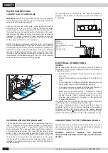
CONNECTION TO THE MAIN LINE
WARNING!
Always use a key and second key for connecting the
coil to the pipes. If the valve is present, adequately isolate the
valve body with insulating material.
Connect the inlet and outlet water pipes respecting what is
indicated on the side of the unit. Properly insulate the water
supply pipes to prevent dripping during cooling operation. On
the outlet tube must be inserted a shut-off valve and in the outlet
pipe a keeper. Also the valve body and holder must be properly
insulated to prevent dripping. Proper insulation should be
installed by the installer. The manufacturer assumes no liability
for the proper performance of the insulation.
NOTE: It is always advisable to install the valve. In the heating
mode, the valve reduces consumption because once it reaches
the temperature, the water circulation is blocked, avoiding thus
waste heat energy. In the cooling function of the valve, blocking
the water circulation when the temperature is reached, it prevents
the indoor heat exchanger continuing to condense water, with
the possibility of undesired dripping on the fl oor. It also reduces
chiller operation contributing to energy savings.
ELECTRICAL CONNECTIONS
WARNING
Before making the electrical connections, make sure that the
supply line is de-energized, making sure that the main switch is
in the OFF position:
- The electrical connections must be performed by qualifi ed
personnel.
-
Ensure that the network is single-phase 230 Vac/1/50 Hz (±
10%).
-
The unit exposed to voltages outside the above limits could
cause malfunction and will invalidate the warranty.
-
The supply line must be equipped with disconnect switch in
compliance with European standard EN60947-3.
- Make sure the electrical system is capable of providing
not only the working current required but also the current
needed to power other equipment already in use. Any
electrical and mechanical alterations or tampering will
invalidate the warranty.
The cables must be long enough, avoiding traction, which can
create bottlenecks or compressions of metal parts.
The power cables must have a length such that in case of
accidental traction of the conductors tend before the grounding
conductor. Connect the ground wire to the relative terminal
marked with the symbol . Check the connection of the grounding.
Observe the safety regulations in force in the installation country.
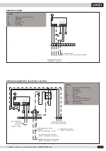
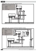
CONNECTIONS TO THE TERMINAL BLOCK
Electrical connections must be made on the terminal strip on the
side of the machine. The meaning of each terminal is indicated
on the label present on the terminal block.
WARNING: STRICTLY OBSERVE THE SPECIFIED
CONNECTIONS, FAILURE TO DO SO WILL CAUSE A BLOWN
ENGINE!
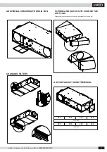
CONDENSATE WATER DRAINAGE
The condensate drain pipe must have a downward slope of at
least 3° and must not show upward strokes or bottlenecks to
allow smooth fl ow of water. It is appropriate that the condensate
drain is siphoned. The condensate drain should be connected to
a rainwater drainage system. Do not use the discharge of white
water or black to avoid possible aspirations of odors in the case
of the evaporation of water contained in the siphon. At the end
of work, check the smooth fl ow of condensate by pouring water
into the tray. The condensate water drainage system must be
installed in a workmanlike manner and should be subjected to
regular monitoring.
The manufacturer is not liable for any damage caused by
dripping in the absence of valve and periodic maintenance of
the drainage.
Siphon
H1=
p/10
H2=((
p/10)/2) + 30
p=
in Pa
H1; H2 = mm


