10
NOTE: DIAGRAMS & ILLUSTRATIONS ARE NOT TO SCALE.
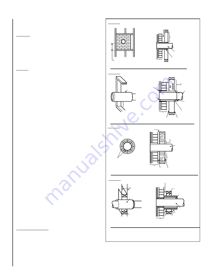
Chimney Connector Systems and Clearances from Combustible
Walls for Residential Heating Appliances (NFPA 211)
Refer to
Figure 8
System A.
Minimum 3.5 in. (90 mm) thick brick masonry wall
framed into combustible wall with a minimum of 12 in. (305 mm)
brick separation from clay liner to combustibles. Fireclay liner (ASTM
C 315, Standard Specification for Clay Flue Linings, or equivalent),
minimum 5/8 in. (16 mm) wall thickness, shall run from outer surface
of brick wall to, but not beyond, the inner surface of chimney flue
liner and shall be firmly cemented in place.
Clearance: 12 in. (305 mm)
System B
. Solid-insulated, listed factory-built chimney length of the
same inside diameter as the chimney connector and having 1 in.
(25.4 mm) or more of insulation with a minimum 9 in. (229 mm) air
space between the outer wall of the chimney length and combustibles.
The inner end of the chimney length shall be flush with the inside of
the masonry chimney flue and shall be sealed to the flue and to the
brick masonry penetration with non-water-soluble refractory cement.
Supports shall be securely fastened to wall surfaces on all sides.
Fasteners between supports and the chimney length shall not pen-
etrate the chimney liner.
Clearance: 9 in. (229 mm)
System C.
Sheet steel chimney connector, minimum 24 gauge [0.024
in. (0.61 mm)] in thickness, with a ventilated thimble, minimum 24
gauge [0.024 in. (0.61 mm)] in thickness, having two 1 in. (25.4
mm) air channels, separated from combustibles by a minimum of 6
in. (152 mm) of glass fiber insulation. Opening shall be covered, and
thimble supported with a sheet steel support, minimum 24 gauge
[0.024 in. (0.61 mm)] in thickness.
Supports shall be securely fastened to wall surfaces on all sides and
shall be sized to fit and hold chimney section. Fasteners used to secure
chimney section shall not penetrate chimney flue liner.
Clearance: 6 in. (152 mm)
System D.
Solid-insulated, listed factory-built chimney length with
an inside diameter 2 in. (51 mm) larger than the chimney connector
and having 1 in. (25.4 mm) or more of insulation, serving as a pass-
through for a single wall sheet steel chimney connector of minimum
24 gauge [0.024 in. (0.61 mm)] thickness, with a minimum 2 in.
(51 mm) air space between the outer wall of chimney section and
combustibles. Minimum length of chimney section shall be 12 in.
(305 mm). Chimney section concentric with and spaced 1 in. (25.4
mm) away from connector by means of sheet steel support plates
on both ends of chimney section. Opening shall be covered, and
chimney section supported on both sides with sheet steel supports
of minimum 24 gauge [0.024 in. (0.61 mm)] thickness.
Supports shall be securely fastened to wall surfaces on all sides and
shall be sized to fit and hold chimney section. Fasteners used to secure
chimney section shall not penetrate chimney flue liner.
Clearance: 2 in. (51 mm)
Additional requirements:
1. Insulation material used as part of wall pass-through system shall be
of noncombustible material and shall have a thermal conductivity of
1.0 Btu-in./hr-ft
2
- ºF (4.88 kg-cal/hr-m
2
- ºC) or less.
2. All clearances and thicknesses are minimums; larger clearances and
thicknesses shall be permitted.
3. Any material used to close up an opening for the connector shall be of
noncombustible material.
4. A connector to a masonry chimney, except for System B, shall extend
in one continuous piece through the wall pass-through system and the
chimney wall to the inner face of the flue liner, but not beyond.
Factory Built
Chimney Length
Air Space – 9 in.
(228.6mm) Min.
Chimney Length
Flush with
Inside of Flue
Min. Clearance
9 in. (229mm)
Chimney
Connector
Use Chimney
Mfrs. Parts to
Attach
Connector
Solid-Insulated
Listed Factory-
Built Chimney
Length
Sheet Steel Supports
Sheet Steel Supports
Sheet Steel Supports
Minimum Chimney Clearance from Masonry to Sheet Steel
Supports & Combustibles – 2 in. (51mm)
Nonsoluble
Refractory
Cement
Minimum chimney clearance to sheet
steel supportrs and combustibles
2 in. (51mm)
Chimney
Connector
2 Air Channels, Each 1
in. (25.4 mm)
2 Ventilated Air
Channels, Each
1 in. (25.4 mm)
Construction of
Sheet Steel
Minimum chimney clearance to sheet steel
supports and combustibles 2 in. (51mm)
Sheet Steel
Supports
Chimney
Connector
Chimney
Section
Air Space – 2 in.
(51mm) Min.
Chimney connector
Chimney length
1 in. (25.4 mm)
air space to
chimney length
Min. Clearance
2 in. (51 mm)
Minimum
12 in. (305mm)
to combustibles
Masonry chimney
constructed to NFPA 211
Masonry chimney
constructed to NFPA 211
Masonry chimney
constructed to NFPA 211
Masonry chimney
constructed to NFPA 211
Minimum chimney clearance to brick
and combustibles 2 in. (51mm)
Minimum clearance
12 in. (305mm)
of brick
Chimney
Chimney
flue
Chimney
flue
Chimney
flue
connector
Fire clay
liner
Figure 8 -
Chimney Connector Systems and Clearances from Combustible Walls
System A
System B
System C
System D