4
NOTE: DIAGRAMS & ILLUSTRATIONS ARE NOT TO SCALE.
TESTING INFORMATION
Your wood stove is dependent upon a properly functioning chimney for
optimum performance. It is a high efficiency appliance that loses much
less heat up the chimney than older appliances and fireplaces. For this
reason it is important to match the stove to the chimney. The chimney
has two functions:
1. It draws combustion air into the appliance (without air, no fuel will
burn) and
2. It exhausts combustion by-products. Your new appliance is what is
known as a “natural draft” appliance.
The appliance depends solely on the natural draft of the chimney system
to draw combustion air into the unit. Draft is the force that moves air from
the appliance up into the chimney. The amount of draft in your chimney
depends on the length of the chimney, local geography, nearby obstructions
and other factors. Too much draft may cause excessive temperatures in
the appliance (overfiring). Slow or inadequate draft equals poor combus-
tion and possible smoking problems. The following are some conditions
that may contribute to poor chimney draft:
1. A chimney too large for your appliance.
2. A chimney with not enough height to produce adequate draft.
3. A chimney with excessive height (this may allow exhaust to cool too
much before exiting, which will stall the rate the exhaust exits).
4. Offsets in the venting system are too restrictive (see
Chimney Guide-
lines)
.
Inadequate draft will cause the appliance to leak smoke into the room
through the stove and the chimney connector joints.
Excessive draft may cause an uncontrollable burn or a glowing red stove
or chimney part.
Overfiring Damage
- If the heater or chimney connector glows, you are
overfiring. Other symptoms may include: Cracking, warping or burning
out of components, plated accessories may turn color, stove glass may
develop a haze, which will not come off with cleaning.
Overfiring of a stove is a condition where excessive temperatures are
reached, beyond the design capabilities of the appliance. The damage
that occurs from overfiring is not covered under the manufacturer’s
limited warranty.
Also see
Troubleshooting
on
Page 20
.
DRAFT REqUIREMENTS
SELECTING THE PROPER VENTING SYSTEM
W.C
. As per NFPA-211 standard (see paragraph below), the installer
must take into account all variables within the installation and install the
appliance in such a manner that satisfies the draft requirements of the
appliance. See
Chimney Guidelines
below to assist you in selecting the
proper venting system for your installation.
American National Standards Institute ANSI/NFPA 211, Standard for
Chimneys, Fireplaces, Vents, and Solid Fuel-Burning Appliances
- See Draft Section:
A chimney or vent shall be so designed and con-
structed to develop a flow sufficient to completely remove all flue and
vent gases to the outside atmosphere. The venting system shall satisfy
the draft requirements of the connected appliance in accordance with the
manufacturer’s instructions.
Chimney Guidelines:
• This appliance requires approximately 12 feet minimum of “effective
draw” provided by the venting system. As a rule of thumb, every 90
degree total direction change in the venting will result in a loss of
approximately 5 feet of “effective draw.” Example: If two 45 degree
offsets are used, subtract 5 feet from the actual vertical vent height
to determine your “effective draw.” In this case if you had 14 feet of
vertical vent, the effective draw would only be approximately 9 feet
(14 ft. - 5 ft. = 9 ft.), therefore it may be necessary to add additional
height to the venting system.
• Do not install an offset within the first two feet above the flue outlet
on the appliance.
• If the venting system is all vertical and the total vent length above the
flue outlet exceeds 14 feet, it is recommended that the 8” to 6” pipe
reducer is used (cat. no. 71134) and a 6” venting system be installed.
At higher elevations, this may not be necessary.
• In well insulated and weather tight homes, it may be difficult to es-
tablish a good draft up your chimney. The poor draft is caused by a
shortage of air in the house. In this situation an Outside Air Kit may
need to be installed
(See
Negative Pressure Warning on
Page 5
and
Outside Combustion Air on
Page 11
)
.
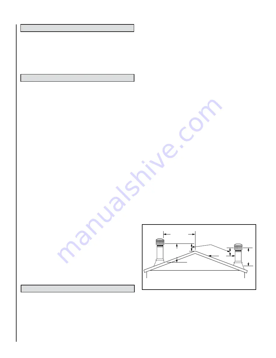
Chimney Height Requirements
The chimney must extend 3’ (.92m) above the level of roof penetration
and a minimum of 2’ (.61m) higher than any roof surface within 10’
(3m) (see below). Check with your local building officials for additional
requirements for your area.
This manual describes the installation and operation of these non-catalytic
wood heaters. These heaters meet the U.S. Environmental Protection
Agency’s emissions limits for wood heaters sold on or after July 1, 1990.
This heater has been developed, tested and constructed in accordance
with the requirements of UL 1482, ULC S627 and HUD standards and
is listed by OMNI Test Laboratories, Portland, OR. It has been approved
for residential, mobile home and alcove installations.
The appliance is merely one component of a larger system. The other
equally important component is the venting system. This is necessary for
achieving the required flow of combustion air to the fire chamber and for
safely removing unwanted combustion byproducts from the appliance.
If the venting system’s design does not promote these ends, the system
may not function properly. Poorly functioning venting systems may create
performance problems as well as be a safety hazard.
A draft test should
read greater than .04’ W.C. (inches water column) and less than .08”
To pass inspection in nearly any jurisdiction, the chimney must meet both
safety and exhaust flow requirements. The (3’ by) 2’ by 10’ rule applies
to both masonry and factory-built chimneys.
* Ref. USA - National Standard, NFPA 211-latest edition and Canada
National Standard CSA B365-01-latest edition. Vents installed with a
listed cap shall terminate in accordance with the terms of the cap’s
listings.
Figure 1
- Chimney Height Requirements
Less than
10' (3 m)
10'
(3 m)
3' (914 mm)
Min.
2’ (610 mm) Min.
(914 mm)
Min.
3'