13
NOTE: DIAGRAMS & ILLUSTRATIONS ARE NOT TO SCALE.
CAUTION: Label all wires prior to disconnection when servic-
ing controls. Wiring errors can cause improper and dangerous
operation.
ATTENTION: Au moment de l'entretien des commandes,
étiquetez tous les fils avant de les débrancher. Des erreurs
de cáblage peuvent entraîner un fonctionnement inadéquat et
dangereux.
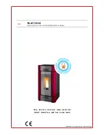
SIT Millivolt Wiring Diagram
If any of the original wire as supplied must be replaced,
it must be replaced with
T ype A WM105
°
C – 18 GA. wire.
Thermopile
TH
T P
TH
T P
* ON/OFF Switch, Optional
Thermostat Remote
Control Receiver
* SWITCH
Figure 10
Step 5: REMOVE MATERIALS FROM FIREBOX
- Remove the packaged
materials from inside of the firebox and set aside (propane conversion
kit, log support cartons, log set and embers).
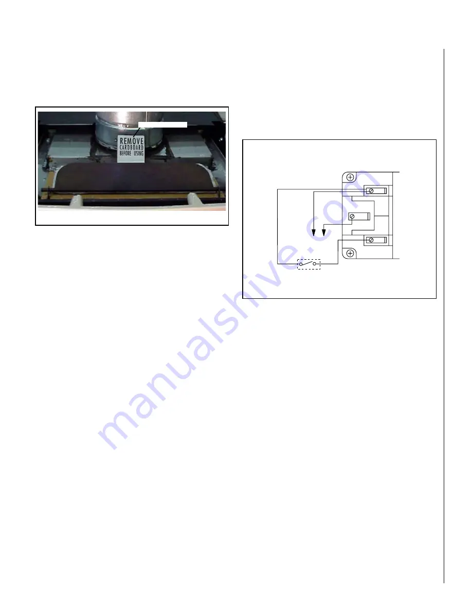
Step 6: REMOVE CARDBOARD
- Remove the cardboard packaging
material from beneath the relief door and discard (see
Figure 9
).
Step 7: INSTALL LP CONVERSION KIT (IF NECESSARY) AND
OPTIONAL ACCESSORIES
Install the LP conversion kit and optional accessories per instructions
provided with the kits (do not install an optional firescreen or brick
liner kit at this point).
A. Optional accessories include a wall thermostat, blower kit, brick liner
kit, warming shelves and a standard or deluxe remote control kits.
B. If a wall-mounted thermostat is selected, mount it in a convenient
location on a wall near the stove. If the warming shelves are being
installed, see Homeowners Manual for installation instructions.
C. Wire the thermostat within the millivolt control circuit using a maximum
of 25 feet of 18 gage, 2 conductor wire. Caution: Do not connect the
optional wall thermostat, gas control valve or control wiring system
of the unit to a 120 volt power supply (residential line voltage)
The gas valve is set in place and pre-wired at the factory on both models
(see
Figure 10
).
Remove Cardboard
Figure 9
RELIEF DOOR
OPTIONAL WALL THERMOSTAT
If an optional wall thermostat is to be installed, install the thermostat
per the manufacturers instructions (provided with the thermostat).
Failure to follow manufacturers instructions could result in a malfunc-
tion. Pay special attention to the thermostat location requirements.
If the location requirements are not adhered to the appliance, erratic
operation or failure may occur.
Do not mount the thermostat where it may be affected by:
• Radiant heat from this appliance, fireplaces, sun or other heat
sources.
• Drafts or dead spots behind doors or in corners.
• Hot or cold air from ducts.
Summary of Contents for CI1500DVF Series
Page 25: ...25 notes ...


