background image

9

NOTE: DIAGRAMS & ILLUSTRATIONS ARE NOT TO SCALE.

v

ertiCal

 v

enting

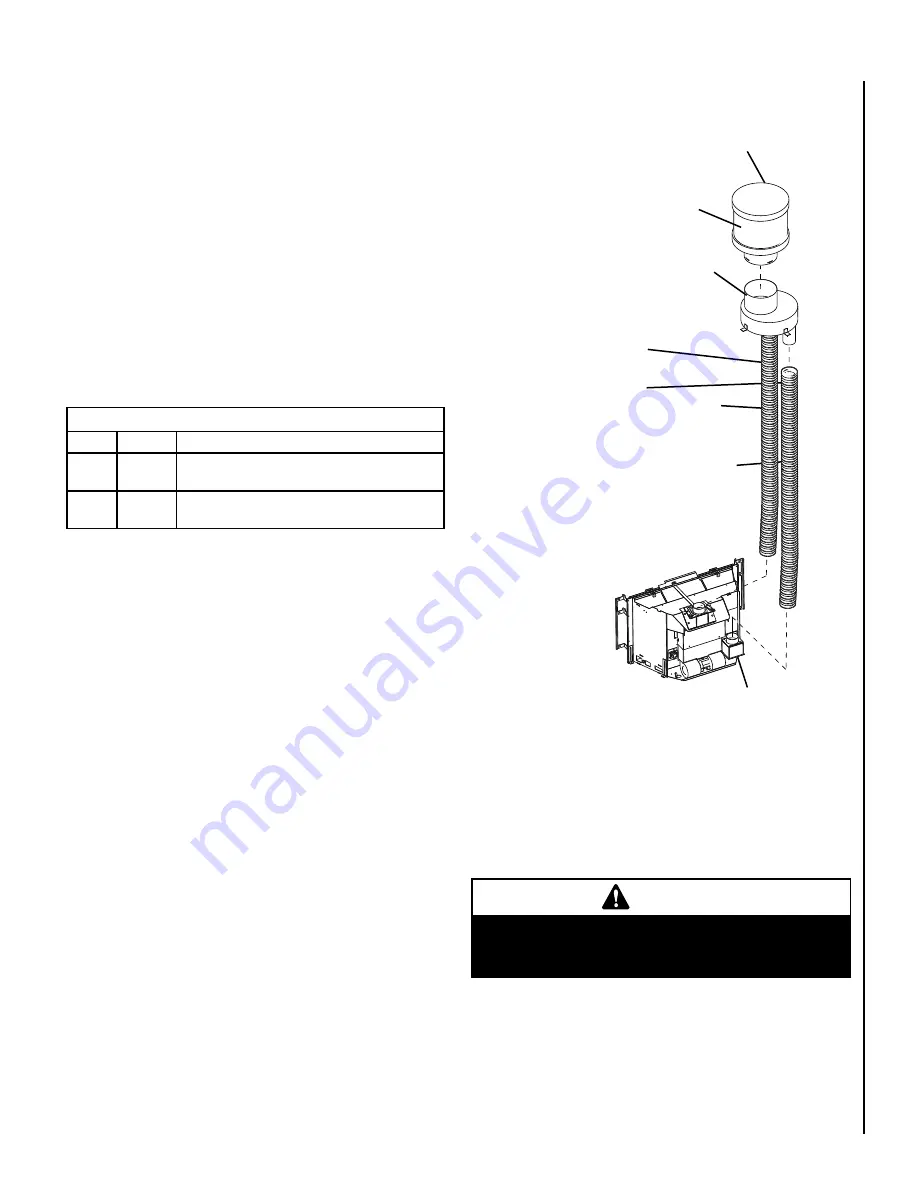
The vent pipes must be connected to the proper collars on 

the unit and the exhaust vent pipe must be connected to the 

termination cap or the unit will not operate. The combustion 

air vent pipe can be connected to the termination cap or it 

can terminate inside the chimney.
The bottom opening of the chimney must be sealed around 

the vent pipes if the combustion air vent is not connected 

to the termination cap. Use unfaced fiberglass insulation to 

seal around the vent pipes. The insulation may give off an 

odor during the first hour of operation.

NOTE:  

The minimum vertical rise (exhaust vent) is 10 feet 

(3.1 M) and the maximum vertical rise is 35 feet (10.7 M). 

These dimensions are measured from the starting collars 

of the unit to the end of the vent pipe.
The fireplace and fireplace chimney must be clean and in good 

working order and constructed of non-combustible materials. 

Inspect chimney cleanouts for proper fit and seal.

* Other approved vent components include; Standard Simpson Dura-vent Co-linear 
Chimney Liner Kit, Direct Vent Termination #991, Liner Termination Kit (includes 
termination connector and flashing) #923GK & 3" x 35' Alum Flex #2280

Vent Kits * 

Cat. No.

Model

Description

H0909

FKDVI

Flex Liner Kit, DVI 3” X 35’

(requires 2, one for exhaust, and one for intake)

H0908

TKDVI

Termination Kit, DVI 

(termination cap and flashing)

Installation

v

enting

 i

nstallation

Your Lennox™ gas insert must be vented to the outside 

in accordance with the current edition of the National Fuel 

Gas Code ANSI-Z223.1 (In Canada, the current CAN/CSA  

B149.1 installation code).  The insert must not be connected 

to a chimney flue serving a separate solid fuel burning ap-

pliance.
This gas insert requires a 3” diameter listed flex liner. The 

vent should terminate with a listed direct vent termination 

cap. The chimney should be sealed around the cap to pre-

vent air and rain from entering the chimney. Adhere to the 

vent manufacturer's instructions for installation and vent 

termination. These appliances are approved for use with 

the following vent kits.

Vertical Cap

Termination 

Connector

Exhaust

Intake

Combustion Air Intake

The  existing  fireplace  chimneys  may  take 

various contours which the flexible liners will 

accommodate. However, keep the flexible liner 

as STRAIGHT as possible, avoid unnecessary 

bending.

Liner Requirements:

Vertical Height Min. = 10 ft. (.1 M)

Vertical height Max. = 5 ft. (10.7 M)

Note: Measured from flue collar on 

unit to the end of the vent pipe or liner

Use " (7 mm) diameter listed gas 

vent liner (UL1777 ONLY) for the 

EXHAUST

Use " (7 mm) diameter listed 

liner (UL 181 or UL1777) for the 

AIR INTAKE.

The flexible vent pipe 

must NOT be allowed to 

sag behind  insert or in 

fireplace flue.

The standard cap 

in Termination Kit, 

H0908,  is  a  high 

wind cap

Make sure that both liners will pass through existing damper area. Remove 

or lock damper to allow the passage of the flexible liners. If the damper 

will not allow the passage of both liners, DO NOT PROCEED FURTHER.  

(If fireplace is masonry) Consult a local mason for removal of the damper 

without risk of structural damage or leakage (if the fireplace is factory 

built) The appliance may NOT be installed into the fireplace.


WARNING

Do not substitute the heat-rated flex liner (UL1777) for the 

exhaust with any other type liner or a fire may result caus-

ing property damage, personal injury or loss of life.

Figure 

Summary of Contents for Direct-Vent Gas

Page 1: ...lez le service des incendies L installation et l entretien doivent tre assur s par un installateur ou un service d entretien qualifi ou par le fournisseur de gaz WARNING If the information in this man...

Page 2: ...lation 10 Surround Panels Installation 11 Face Installation 11 Gas Line Installation 12 Gas Pressure Requirements 12 LP Natural Gas Supplies 12 Air Shutter Adjustment 12 13 Operating Instructions 13 1...

Page 3: ...bsence of local codes with the National Electrical Code ANSI NFPA 70 latest edition In Canada the current CSA C22 1 Canadian Electrical Code latest edition Your Lennox gas insert must be equipped for...

Page 4: ...ucture Combustionairisdrawnfromoutside the structure When installing in a factory built fireplace the fireplace grate must be removed and the damper must be removed or secured open WARNING THIS FIREPL...

Page 5: ...The individual manual shut off must be a T handle type valve Commonwealth Of Massachusetts Requirements Note The following requirements reference various Massachusetts and national codes not contained...

Page 6: ...ired Insert Body Packaging List 1 Insert Body with Burner Cassette 1 Log Set 1 Bag of Embers 1 Fasteners 6 slotted 1 4 truss screws 6 speed nuts 9 spring clips 3 plastic adhesive wire restraints 1 Ins...

Page 7: ...ortionofthechimneysystemshowssigns of structural or mechanical weaknesses such as cracks leaky joints corroded or warped surfaces the faulty portion must be repaired or replaced prior to installing th...

Page 8: ...n the screws Repeat these steps for each adjusting leg G 13 330mm 10 254mm 0 0mm H 0 0mm 2 21mm 4 102mm E H F G J C L MANTEL TRIM Mantel Trim Hearth Floor Protection E 31 1 2 800mm from Top Facing to...

Page 9: ...1installationcode Theinsertmustnotbeconnected to a chimney flue serving a separate solid fuel burning ap pliance This gas insert requires a 3 diameter listed flex liner The vent should terminate with...

Page 10: ...the flue collar is removable see Flue Collar Connection If the factory built fireplace has no gas access hole s pro vided an access hole of 1 1 2 37 5 mm or less may be drilled through the lower sides...

Page 11: ...ure loosely Face Installation The faces come with hooked brackets To install the face hang the hooked brackets on the surround brackets C in Figure 12 Figure 12 A B C Spring Handle Latches Door Mounti...

Page 12: ...lve must be disconnected from the gas supply piping system during any pressure testing of that system at test pressures in excess of 1 2 psig The appliance must be isolated from the gas supply piping...

Page 13: ...ghting the pilot follow these instructions exactly B BEFORE LIGHTING smell around the appliance area for gas Be sure to smell next to the floor because some gas is heavier than air and will settle on...

Page 14: ...knob slightly and turn clockwise to OFF Do not force This appliance needs fresh air for safe operation and must be installed so there are provisions for adequate combustion and ventilation air WARNIN...

Page 15: ...When the blower turns on the sound of rushing air may be heard The blower sounds may be reduced by adjusting the speed control located on the blower assembly Also a slight clicking sound may be heard...

Page 16: ...e to determine the proper gage of wire for the thermostat or wall switch connections This table refers to the total length of the wire out to the switch and back The thermostat must be a millivolt typ...

Page 17: ...le and extend across the main burner ports Be careful not to back the screw out of its threads Replace the cover and check for gas leaks using a gas leak test solution oCheck that the area around the...

Page 18: ...reference Remove the insert face glass door and log set All of these items are fragile so handle them with care Next remove the nine allen head screws around the outside of the panel fastened to the b...

Page 19: ...pilot lights turn off pilot and trigger the igniter again If pilot lights an intermittent gas air supply may be the problem if longer purge will not light check gap between electrode and pilot should...

Page 20: ...e Main Burner LP 53 H5951 Orifice High Altitude Main Burner LP 54 H5464 Conversion Kit NG to LP H5465 Conversion Kit LP to NG H6013 Blower w Mounting Bracket H5875 Blower Snap Switch H5655 Blower Spee...

Page 21: ...ase de H l appareil aux combustibles HOMOLOGU FOYER RADIANT PR FABRIQU AU GAZ INSERTION DE FOYER AU GAZ NE PAS UTILISER AVEC DU COMBUSTIBLE SOLIDE TEST SELON LA NORME ANSI Z21 88 2005 CSA 2 33 2005 FO...

Page 22: ...un agent de service ou un fournisseur de gaz Si vous op rez cet appareil sans qu il ne soit correctement raccord un conduit d vacuation vous pourriez risquer d tre empoisonn au monoxyde de carbone CO...

Page 23: ...on about your fireplace Please contact your Lennox Hearth Products dealer for any questions or concerns For the number of your nearest Lennox Hearth Products dealer please call 877 247 3673 Replacemen...

Page 24: ...2007 Lennox reserves the right to make changes at any time without notice in design materials specifications prices and also to discontinue colors styles and products Consult your local distributor fo...

Reviews: