10
NOTE: DIAGRAMS & ILLUSTRATIONS ARE NOT TO SCALE.
LENNOX HEARTH PRODUCTS • MERIT PLUS
®
B-VENT GAS FIREPLACES (MPB33/35/40/45) • CARE AND OPERATION INSTRUCTIONS
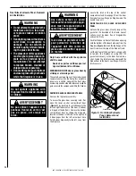
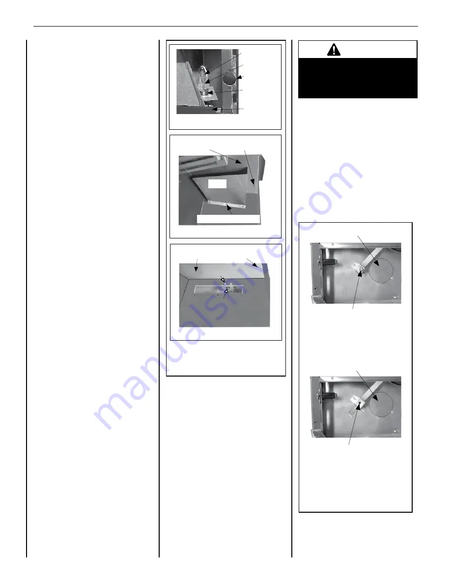
Scoop
Scoop Securing Screws
Firebox Top
Lintel Securing Screw
Hole in Cabinet Top
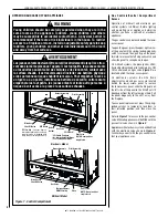
Figure 4 - Safety Limit Switch
Blocked Flue Safety Limit Switch Location, Inside
View of Firebox, Top/Right Side Intersection
Detail A
Firebox Top
Limit Switch
Limit Switch/Bracket
Securing Screws
Lintel Securing-Screw
Hole in Cabinet Top
View Without Scoop
Detail C
Detail B
Wire
Terminals
Back Of
Limit
Switch
Cabinet
Corner
Door
Frame
Reset Button
NOTE: Do not assume the outside air vent
system is installed.
To open the outside air shutter complete the
following steps.
1.
Open the bottom control access panel.
2.
Reach into the control compartment and
pull the combustion air control lever all
the way out.
The outside air shutter should be fully open
when the fireplace is in use and completely
closed when the fireplace is not being used.
Closing the air shutter when not in use will
prevent outside cold air from entering the
building.
Replacing The Safety Limit Switch
To replace the blocked vent safety limit switch,
refer to
Figure 4, Details B & C
)
.
NOTE
: This procedure should only be
performed by a qualified service technician.
1.
Turn electrical power off before
beginning this procedure.
2.
Lower the bottom control compartment
access panel.
3.
Remove the glass enclosure panel by
unfastening the latch (located in the center
of the unit front opening, under the firebox
floor) securing the glass enclosure panel.
4.
Remove the glass enclosure panel by
tilting it outward at the bottom and lifting it
up. Carefully set the door aside to protect
it from inadvertent damage
(see
Figure 6
on Page 12
)
.
5.
Remove the three (3) screws securing
the lintel, and then remove the lintel. One
of the lintel cabinet top holes is shown in
Figure 4, Detail B
.
6.
Remove the three (3) screws securing the
scoop, and then remove the scoop
(see
Figure 4, Detail B
)
.
7.
Remove the two (2) screws securing the
safety switch bracket, and remove the
switch/bracket assembly, with low voltage
wires attached, through the side panel slot
into the firebox
(see
Figure 4, Detail C
)
.
8.
Replace the switch.
9.
Reinstall the switch/bracket assembly.
10.
Reinstall the scoop and lintel.
11.
Reinstall the glass enclosure panel.
12.
Raise the bottom control compartment
access panel.
13.
The appliance should then relight and
remain lit. If this does not occur, check
unit for a blocked vent condition.
WARNING
Do not operate the shutoff lever
unless a complete outside
combustion air system has been
installed with the appliance.
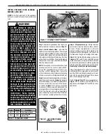
Outside Air Control Lever
Outside Air Control Lever
Securing Screw
Air Shutter in Closed Position
Outside Air Control Lever
Securing Screw Removed
Air Shutter in Open Position
Outside Air Control Lever
Figure 5 - Combustion Air Control
Lever and Securing
Screw Location
Outside Combustion Air Controls
Many appliances are equipped with an outside
(make-up air) vent system designed to
provide the appliance with outside make-up
air for combustion while in operation.
The combustion air control lever for the
outside air system is standard on all
appliances but should not be operated if the
complete system is not installed (see
Figure
5
)
. When the complete outside air vent
system is installed, the installer will remove
the securing screw from the combustion air
control lever located on the left side of the
bottom fireplace opening.
If the securing screw has not been removed
and you have reason to believe that you have
a complete outside air system, contact your
dealer to have your appliance inspected for
the presence of the complete system.


