background image

Clearances to non-combustibles

Non-combustible surfaces are defined as brick, metal, marble, concrete
etc. and also a number of man-made materials impervious to flame. If in
doubt refer to the material manufacturer for further information before
proceeding with installation.

Clearances to the sides of the appliance are 4”. Clearance to the front of
the appliance is 20”. 

The back of the appliance may be installed directly onto a non-combustible
wall, providing the area behind the appliance is flat and does not interfere
with the various vent holes in the back panel of the appliance.

The appliance may be installed with or without a non-combustible hearth. If
a hearth is fitted, the size and design may be as desired.

A non-combustible shelf of any depth may be positioned above the
appliance provided it is no closer than 16” from the top of the appliance
glass panel and the wall above the appliance is non combustible.

Clearances to combustible materials

Combustible materials are defined as wood, fabrics, or other materials
likely to combust if exposed to flame. Generally, any material, which is likely
to discolour, melt or misshape when exposed to moderate heat, should be
considered as a combustible material or surface. 

Clearance to the sides of the appliance are 4” but curtains, drapes and
other fabrics are not permitted within a distance of 20” of the appliance
sides. No such materials are permitted directly above the appliance
regardless of distance. 

The minimum clearance to the ceiling above the appliance is 32” measured
from the top of the appliance glass panel.

Combustible materials should not be positioned directly in front of the
appliance within a distance of 40”.

Under no circumstances should any electrical equipment e.g. plasma
screen TV sets etc. be positioned on the wall above the appliance. The
appliance is designed to be wall mounted alone and not in conjunction with
any type of combustible fire surround. 

No combustible shelves should be positioned on the wall above the
appliance. 

It should be established that any mirrors or picture frames etc. to be
positioned on the wall above the appliance are able to withstand prolonged
exposure to moderate heat and moisture before proceeding with their
installation.

The back of the appliance may be installed directly onto a combustible wall,
providing it is flat and does not interfere with the various vent holes in the
back panel of the appliance. The wall must be structurally sound and
constructed from a material capable of withstanding moderate heat.
Finished plaster, conventional wall paper and dry-lined plasterboard are
examples of suitable materials. Materials such as flock, blown vinyl and
embossed paper which are sensitive to even small amounts of heat should
be avoided as scorching and or discoloration may occur over time.

If the appliance is to be mounted on a dry-lined wall or a timber framed
construction wall then the integrity and ability of the wall to carry the weight
of the appliance must be confirmed. It is important in these circumstances
that any vapor control barrier is not damaged, and that any structural
members of the house frame are not damaged. 

The appliance may be positioned as close to a solid floor (i.e. stone,
wooden laminate etc.) as the particular design of fire frame permits,
however it is not permitted to install the appliance within 4” of carpet, rugs
or fabric materials of any kind. This dimension is measured vertically to the
bottom of the appliance frame.

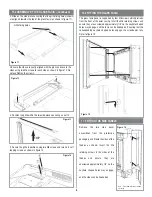
Gas connection :

The heater gas inlet connection is 3/8” NPT at the

regulator, located below the burner, in the center of the heater. 

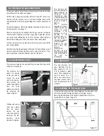
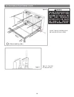
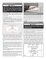
There are four possible
entry points for the gas
supply pipework to enter
the appliance firebox.
These entry points are
‘knock out’ type holes
(shown in figure 1).
Non-concealed gas
connections may be
made using the entry
points on the base of the
firebox. A

concealed

gas connection may be
made using the knock
out hole in the centre
back of the firebox.
Select the most
appropriate entry point and knock out the relevant hole. 
If a concealed gas connection is to be made, the supply pipe should always
be sleeved through walls and floors using the shortest possible route. 

For concealed supply pipe routing, pipes must (where possible) be vertical
and providing there is sufficient wall thickness available, they should be
placed in pipe chases. Horizontal pipe runs should be avoided where
possible.  Prior to chasing a solid wall, an inspection should be made to note
the proximity of any cables/sockets outlets which may already be buried.
Pipes must be secured using suitable clips and protected against corrosion.
Ideally factory finished protected pipework and fittings should be used.
Joints should be kept to a minimum and compression fittings must not be
used. The pipework installation must be tested for soundness before any
protection is applied and/or the pipework and fittings are buried.

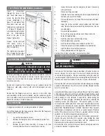
After having selected the final mounting position of the appliance, taking
into account the site requirements as specified in section 7 of these
instructions, the integrity of the wall, and the feasibility of the proposed
supply  pipe routing, the firebox of appliance may be secured to the wall. 

5

7.0 SITE REQUIREMENTS (continued)

8.0 PREPARING THE APPLIANCE

9.0 MOUNTING THE APPLIANCE

Figure 1

DO NOT USE A BLOWER INSERT, HEAT EXCHANGER
INSERT OR OTHER ACCESSORY NOT APPROVED FOR
USE WITH THIS HEATER.

WARNING

DO NOT ALLOW ANY FANS TO BLOW DIRECTLY INTO
THE FIREPLACE. AVOID ANY DRAFTS THAT ALTER
BURNER FLAME PATTERNS.

WARNING

Summary of Contents for SCANDIUM-NG

Page 1: ...heat for a while after shutting off the appliance Severe burns may result Carefully supervise children in the same room as appliance Duetohightemperatures theapplianceshouldbelocatedoutoftrafficandawayfromfurnitureordraperies Do not place clothing or other materials on or near this appliance Improper installation adjustment alteration service or maintenance can cause injury or property damage Refe...

Page 2: ...riefing the customer 9 19 0 Servicing 9 20 0 Servicing the Burner 9 21 0 Pilot Assembly 10 22 0 Catalysts 10 23 0 Testing for Firebox Leakage 10 24 0 Cleaning 10 25 0 Lighting Instructions 11 26 0 To Turn off gas to Appliance 11 27 0 Troubleshooting Guide 12 28 0 Replacement Parts 12 29 0 Positioning of field assembled parts 13 1 0 GENERAL INFORMATION 2 0 PACKAGING LIST 4 0 IMPORTANT SAFETY INFORM...

Page 3: ...th 248 CMR c Unvented natural gas fired space room heaters shall be installed in accordance with their listings and the manufacturer s instructions Proper clearances to combustibles shall be maintained In no case shall the clearances be such as to interfere with combustion air and accessibility d Installations shall be of a permanent type with a permanently piped fuel supply in accordance with 248...

Page 4: ...rchaser a copy of 527 CMR 30 upon sale of the unit Please refer to section 4 0 on page 2 of this manual This Lennox Hearth Products unvented gas room heater is certified by OMNI Test Laboratories Inc to ANSI Z21 11 2 2007 standard This heater shall not be installed in a confined space or unusually tight construction unless provisions are provided for adequate combustion and ventilation air The Nat...

Page 5: ...n vinyl and embossed paper which are sensitive to even small amounts of heat should be avoided as scorching and or discoloration may occur over time If the appliance is to be mounted on a dry lined wall or a timber framed construction wall then the integrity and ability of the wall to carry the weight of the appliance must be confirmed It is important in these circumstances that any vapor control ...

Page 6: ...ntilation holes of the appliance The wall onto which the appliance is installed must be flat Install only on a vertical surface Avoid sloped surfaces Installation onto anything other than a vertical wall may result in fire damage or injury A full size fitting template is supplied to assist with wall mounting Mark the positions shown as Fixing Points on the wall If the appliance is to be mounted on...

Page 7: ... that is left on the pipes fittings can result in corrosion over time A Light the appliance refer to the lighting instructions label in the con trol compartment or on page 11 B Brush all joints and connections with the gas leak test solution to check for leaks If bubbles are formed or gas odor is detected turn the gas control knob off pilot on to the OFF position Either tighten or refasten the lea...

Page 8: ...casing Insert the M6 retaining screws and ensure they are unscrewed approximately 1 8 so the keyhole shaped holes may engage and the facia can be hooked on Ensuring that the corresponding keyhole shaped holes engage the screwheads fully Refer to figure 15 Remove the two side panel assemblies from the protective packaging and fit onto the sides of the firebox as shown Insert the M6 retaining screws...

Page 9: ... Refit the glass door assembly 13 Refit the facia Refitting as described in section 15 0 14 Check the purpose provided ventilation is unobstructed 15 Light the fire and test setting pressures 16 Check safe operation of the appliance For specific servicing instructions see relevant sections First remove the front Glass facia as described in Section 16 0 only in reverse remove the valve cover 4 scre...

Page 10: ...as concentrations in terms of per centage To convert from parts per million ppm to a percentage divide the ppm figure by 10 000 Examples 35ppm 0 0035 15ppm 0 0015 5ppm 0 0005 Now divide the concentration of carbon monoxide CO expressed in percent by the concentration of carbon dioxide CO2 to obtain the appliance combustion ratio The combustion ratio of the gasses emitted by the catalytic convertor...

Page 11: ...tion Figure 19 and hold there for a few seconds Note If you are running the heater for the first time or after an extended period of non use it will be necessary to press the control knob all the way in for 30 seconds to allow air to bleed out of the gas piping 8 Continue turning counterclockwise through the spark click to the PILOT light position ensuring the pilot has lit If not turn the knob fu...

Page 12: ...T STAY LIT Pilot flame shrinks when fire is on high Poor gas flow to fire check pressure with fire on high If pressure is low remove any restriction in pipework or valve Check all pipework is adequately sized Check meter pressure is adequate If the pilot will not stay lit there is a problem with dirt the gas supply or the thermocouple needs replacement Modifications are dangerous and can have a se...

Page 13: ...check for correct pilot flame 29 0 POSITIONING OF FIELD REMOVABLE PARTS Figure 21 4 off burner installation positions FAILURE TO POSITION THE PARTS IN ACCORDANCE WITH THESE DIAGRAMS OR FAILURE TO USE ONLY PARTS SPECIFICALLY APPROVED WITH THIS HEATER MAY RESULT IN PROPERTY DAMAGE OR PERSONAL INJURY WARNING ...

Page 14: ...se The Product is designed to burn either natural or propane gas only Burning conventional fuels such as wood coal or any other solid fuel will cause damage to the Product will produce excessive temperatures and will result in a fire hazard c damages caused by failing to provide proper maintenance and service in accordance with the instructions provided with the Product d damages repairs or ineffi...

Page 15: ...e con atención a los niños que estén en la misma habitación que el aparato Debido a las altas temperaturas generadas el aparato debe ubicarse en un lugar con poco tránsito alejado de muebles y cortinas No coloque ropa ni otros materiales sobre o cerca de este aparato La instalación el ajuste la modificación la revisión o el mantenimiento inadecuados pueden causar daños materiales o lesiones person...

Page 16: ...de vidrio 21 16 0 Montaje del panel decorativo de vidrio 22 17 0 Colocación de los paneles laterales 22 18 0 Información al cliente 23 19 0 Mantenimiento 23 20 0 Mantenimiento del quemador 23 21 0 Montaje del piloto 24 22 0 Catalizadores 24 23 0 Comprobación de fugas de la cámara de combustión 24 24 0 Limpieza 24 25 0 Instrucciones de encendido 25 26 0 Cómo cerrar el paso de gas al aparato 25 27 0...

Page 17: ...to de oxígeno ODS y contar con la aprobación establecida en 248 CMR c Los calentadores de gas natural sin salida de humos deben instalarse según sus especificaciones y las instrucciones del fabricante Debe mantenerse el espacio libre adecuado hasta los materiales combustibles En ningún caso las características del espacio libre obstaculizarán el aire de combustión ni la accesibilidad d Las instala...

Page 18: ... proporcionar a cada comprador una copia de 527 CMR 30 en el momento de la venta de la unidad Consulte la sección 4 0 en la página 2 de este manual Este calentador de gas sin salida de humos de Lennox Hearth Products está certificado por OMNI Test Laboratories Inc con arreglo a la norma ANSI Z21 11 2 2007 Este calentador no debe instalarse en un espacio confinado o en una construcción inusualmente...

Page 19: ...pel vinílico y papel en relieve que son sensibles incluso a niveles bajos de calor pueden resultar chamuscados y o decolorados con el tiempo Si el aparato va a montarse en una pared revestida de cartón yeso o en una pared de armazón de madera debe confirmarse la integridad de la pared y su capacidad para soportar el peso del aparato Es importante en estas circunstancias no dañar cualquier barrera ...

Page 20: ...lación del aparato La pared en la que se instale el aparato debe ser plana Instale el aparato en una superficie vertical únicamente Evite las superficies desparejas La instalación del aparato en una pared que no es vertical puede provocar un incendio daños materiales o lesiones físicas Se suministra una plantilla de instalación de tamaño real para ayudar a realizar esta tarea Marque en la pared lo...

Page 21: ...os acoplamientos puede producir corrosión con el tiempo A Encienda el aparato consulte la etiqueta de instrucciones de encendido del compartimento de control o de la página 11 B Con un cepillo cubra todas las juntas y conexiones con la solución para pruebas de fugas de gas para verificar que no hay fugas Si se forman burbujas o se detecta olor a gas haga girar la la perilla de control del gas apag...

Page 22: ...egúrese de que sobresalen unos 1 8 para poderlos introducir en los orificios en forma de bocallave y para que se enganche el panel Asegúrese de que los tornillos están correctamente introducidos en los orificios en forma de bocallave Consulte la figura 15 Retire los dos conjuntos de panel lateral del embalaje protector y móntelos en los laterales de la cámara de combustión según se indica Introduz...

Page 23: ...n la sección 15 0 14 Compruebe que la ventilación integrada no está obstruida 15 Encienda el calentador y compruebe las presiones 16 Compruebe que el aparato funciona de manera segura Consulte las secciones correspondientes si necesita instrucciones de mantenimiento específicas Primero retire el panel decorativo de vidrio delantero según se describe en la Sección 16 0 pero en sentido inverso retir...

Page 24: ...ambas concentraciones de gas como porcentaje Para convertir desde partes por millón ppm a un porcentaje divida la figura en ppm por 10 000 Ejemplos 35ppm 0 0035 15ppm 0 0015 5ppm 0 0005 Ahora divida la concentración de monóxido de carbono CO expresada como porcentaje por la concentración de dióxido de carbono CO2 para obtener la razón de combustión del aparato La razón de combustión de los gases e...

Page 25: ...presionada en esa posición durante unos segundos Nota Al encender el calentador por primera vez o después de un periodo prolongado sin usarlo será necesario mantener la perilla presionada hasta el fondo durante unos 30 segundos para purgar todo el aire de las tuberías de gas 8 Continúe haciendo girar en el sentido contrario a las agujas del reloj pasando por el clic de la chispa hasta la posición ...

Page 26: ...CA MODIFIQUE NI DOBLE EL TERMOPAR PARA HACER QUE EL PILOTO SE MANTENGA ENCENDIDO La llama del piloto se reduce cuando el Flujo defectuoso de gas al calentador compruebe la presión con el calentador en Alto calentador está en Alto Si la presión es baja elimine cualquier restricción en la tubería o la válvula Compruebe que toda la tubería sea del tamaño correcto Compruebe que hay suficiente presión ...

Page 27: ...l de la llama del piloto 29 0 UBICACIÓN DE PIEZAS SUSTITUIBLES IN SITU Figura 21 4 posiciones de instalación del quemador EL NO UBICAR LAS PIEZAS EN LOS LUGARES SEÑALADOS EN ESTOS DIAGRAMAS O LA UTILIZACIÓN DE PIEZAS NO HOMOLOGADAS OFICIALMENTE PARA EL USO CON ESTE CALENTADOR PUEDEN CAUSAR DAÑOS MATERIALES O LESIONES PERSONALES ADVERTENCIA ...

Page 28: ...e ser sometido a un uso normal El Producto está diseñado para usarse con gas natural o propano exclusivamente El uso de combustibles convencionales como madera carbón o cualquier otro combustible sólido dañará el Producto generará temperaturas excesivas y provocará un peligro de incendio c los daños que se produzcan por no proporcionarse el debido mantenimiento de acuerdo con las instrucciones pro...

Reviews: