background image

19

NOTE: DIAGRAMS & ILLUSTRATIONS ARE NOT TO SCALE.

DOOR HINGES:  

If door hinges need lubricating, use an anti-seize com-

pound (never use oil) available from your Lennox Hearth Products dealer.

DOOR LATCH: 

 If your door latch fails to latch tightly and the gasket is 

in good condition, place a length of pipe (cheater bar) over the inside 

portion of the door handle and bend slightly toward the door until the 

proper adjustment is obtained. If the door handle does not close easily, 

apply high temperature anti-seize to the striker.

DOOR GASKET:  

Periodically check gasket to make sure it is not over-

compressed. If compressed, replace with a special woven Door Rope. 

(Don’t try substituting rope, only use special Lennox Hearth Products 

Door Rope).

PLATED ACCESSORIES:

  Clean only with household type glass cleaner 

and a very soft cotton cloth. Other products may damage plated finish, 

paint and gaskets.

BAFFLE BLANKET:

  Your baffle blanket should be inspected during every 

chimney cleaning. If the baffle blanket is compressed or heavily stained, 

it should be replaced. Heavy creosote stains or matting is an indication 

of improper use and your burning habits should be reviewed.

GLASS CLEANING:

  Only clean glass with products specifically made to 

use on wood stoves. Other products could damage gaskets and paint. 

Never scrape glass with a razor blade. This can pit the glass and make it 

impossible to clean in the future.

WINDOW GASKET:

  The window gasket can be checked by running the 

flame of a match near the gasket and around the door. If the flame is 

drawn in around the window, the gasket should be replaced.

DOOR HANDLE:

  Door handle may become tight as you use the stove. 

Free the handle up by using dry graphite supplied with the stove. The 

directions are included with the graphite.

       WARNING 

Inspect and clean chimney and connector frequently. 

Under certain conditions of use, creosote buildup 

may occur rapidly. 

MAINTENANCE

       CAUTION 

Cleaning  Glass:  Ensure  appliance  is  cold  prior 

to  cleaning  glass.    A  commercial  glass  cleaner 

designed for stoves is recommended.  Do not use 

abrasive cleaners. Do not clean with any materials, 

which may scratch or otherwise damage the glass.  

Scratches on the glass can develop into cracks or 

break.  Inspect the glass regularly.  If you detect a 

crack, extinguish the fire and contact your dealer 

for a replacement.

GLASS CLEANING GUIDELINES
WARNING: DO NOT CLEAN GLASS WHEN APPLIANCE IS HOT!

Glass on any wood stove or fireplace insert will not stay perfectly clean. 

Here are some guidelines for cleaning and caring for the glass:

•   Ensure the stove or fireplace insert is cold prior to cleaning glass.

•   This appliance is designed to provide a flow of air over the inside of 

the glass, where along with high heat helps inhibit build-up on the 

glass.  When build-up occurs, a commercial glass cleaner designed 

for stoves is recommended.  Regular household glass cleaners will 

not clean creosote.

•   Do not use abrasives such as steel pads, steel wool or oven cleaner 

as they will scratch the glass. Never scrape glass with a razor blade 

as this may pit the glass and make it impossible to clean in the future.

•   Do not use chemical glass cleaners as they may damage the gaskets 

or painted surfaces.

TIPS FOR KEEPING THE GLASS CLEAN

•   Burn only dry seasoned cord wood.  

Wet wood = Dirty glass.

•   A short, hot fire (15 - 20 minutes) may help to clean off some of the 

normal buildup. 

Lower burns = more build-up. Higher burns = less 

build-up.

•   Keep freshly loaded wood away from the glass.

•   After reloading, allow all the wood to catch flame before dampering 

down the stove or fireplace insert. 

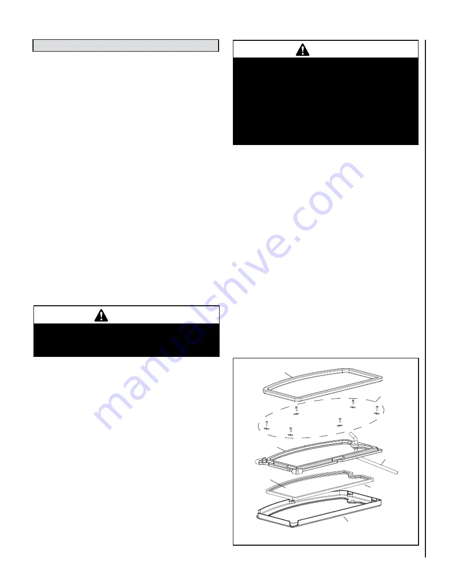
GLASS REPLACEMENT INSTRUCTIONS

Step 1.   Remove Door Assembly 

- Open door to remove E clip from the upper 

hinge pin.  Remove upper hinge pin by pulling up while holding the op-
posite side of the door.  Lift door out of the lower hinge pin and place 
face down on a soft surface.

Step 2.


Remove Door Back Screws (6 ea.)

 - Using a 5/32” allen wrench remove 

the 6 retainer screws from the faceplate.  To locate screws, peel back the 
door gasket as necessary.

Step 3.


Disassemble Door Assembly

 - Flip door assembly over to be face up.  

Separate faceplate from door back by pulling up on faceplate.

Step 4.


Remove  Glass

  -  Carefully  remove  broken  glass  one  piece  at  a  time 

(protective gloves are recommended)

Step 5.


Install New Glass Assembly

 - Install the new glass with gasket in recess 

on door back (use only factory supplied 5mm ceramic glass.  Do not 
substitute).

Step 6. 


Reinstall Faceplate and Screws 

- Reinstall faceplate onto door back 

and while holding the door assembly together flip the assembly back 
onto it’s face.  Carefully reinstall the screws.  Be very careful not to 
overtighten the screws (this could result in glass breakage when the 
stove or fireplace insert is hot) and it is highly recommended to use anti 
seize on the screws.

Step 7. 


Reinstall Door

 - Set door assembly back into the lower hinge mount 

while holding the handle side of the door up.  Place the upper hinge 
pin back in the mount and door assembly.  Reinstall the E clip that was 
removed.

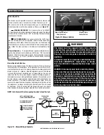
Figure 20

Faceplate

Glass Gasket

Glass

Door Back

Handle Rod

Door Gasket

Screws and 

Washers

Summary of Contents for STRIKER S160

Page 1: ...Portland A French manual is available upon request Order P N 775214CF Ce manuel d installation est disponible en francais simplement en faire la demande Numéro de la pièce 775214CF This appliance must be properly installed and operated in order to prevent the possibilityofahousefire Pleasereadthisentireinstallationandoperation manual before installing and using your wood stove Failure to follow th...

Page 2: ...tor 6 Components Required for Installation 6 Installation Clearances 7 USING THIS MANUAL Please read and carefully follow all of the instructions found in this manual Please pay special attention to the safety instructions provided in this manual PRODUCT IS SUBJECT TO CHANGE WITHOUT NOTICE Typical Installation Figures 8 Chimney Installation 9 Manufactured mobile Home Installations 9 Chimney Wall P...

Page 3: ...ing season to check for soot and creosote accumulations Any accumulations over 1 8 thick should be removed by a professional chimney sweep Do not attempt to burn out heavy creosote accumulations with a hot fire If large ac cumulationsareoccurring reviewyourburningprocedures 14 Ifacreosotefireshoulddevelop thefiredepartmentshould be called immediately and then attempts should be made to control the...

Page 4: ...not come off with cleaning Overfiring of a stove is a condition where excessive temperatures are reached beyond the design capabilities of the appliance The damage that occurs from overfiring is not covered under the manufacturer s limited warranty Also see Troubleshooting on Page 20 Draft Requirements Selecting the Proper Venting System To pass inspection in nearly any jurisdiction the chimney mu...

Page 5: ...n soil or otherwise locally dispersed they should be retained in the closed container until all the cinders have thoroughly cooled Ashes can ignite up to 72 hours after removal from the stove Creosote Formation and Need for Removal When wood is burned slowly it produces tar and other organic vapors which combine with expelled moisture to form creosote The creosote vapors condense in the relatively...

Page 6: ...shall be UL listed Residential chimney systems must be from the same brands as listed for mobile homes but connector pipe may be double wall single wall or single wall with shield as listed above This appliance may be vented into a code approved masonry chimney with flue liner Warning Chimneyconnectormustbeingoodconditionandkeptclean Do not install damaged parts All of the stove connector pipe use...

Page 7: ...ada 8 200mm from sides and back of unit u Dimensions to Stove Body v Clearances may only be reduced by means approved by the regulatory authority Mobile Home USA only PIPE INSTALLATION Nu Pu T 6 Single Wall Residential or Alcove 30 762mm 36 914mm USA 58 1 2 CAN 1645mm vSingle w Pipe Shield Residential or Alcove 30 762mm 36 914mm USA 52 CAN 1486mm Double Wall Air Cooled Residential or Alcove or Mob...

Page 8: ...ing 6 Diameter Rigid Stainless Steel Liner Figure 5 Typical Installation Figure 6 Connected to a Masonry Chimney Floor Protector Floor Protector Fasten each stove pipe connection with at least 3 sheet metal screws Single wall stove pipe must not pass through attics closets walls or ceilings It is used to connect this appliance to a factory built or masonry chimney INSTALL VENTING SYSTEM PER VENT M...

Page 9: ...side air kit see Page 27 for ordering information and the stove must be secured to the floor and grounded to the mobile home chassis Install Outside Air Kits per instructions on Page 11 INSTALL VENTING SYSTEM PER VENT MANUFACTURERS INSTRUCTIONS Fasten stove pipe to flue collar using 3 sheet metal screws SecureStove to floor Grounded to Steel Chassis using a 8 AGW copper wire or equivalent Chassis ...

Page 10: ...ll be 12 in 305 mm Chimney section concentric with and spaced 1 in 25 4 mm away from connector by means of sheet steel support plates on both ends of chimney section Opening shall be covered and chimney section supported on both sides with sheet steel supports of minimum 24 gauge 0 024 in 0 61 mm thickness Supports shall be securely fastened to wall surfaces on all sides and shallbesizedtofitandho...

Page 11: ...nts upon receipt and check for any damaged or missing parts If there is hidden damage notify your freight company or Lennox Hearth Products dealer immediately CAUTION Wear gloves during installation in case of sharp edges on the stove Leg Installation 1 Carefully place stove on its back Be careful not to scratch the stove use a piece of cardboard or carpet to protect the back of the stove 2 Mount ...

Page 12: ... fastening the stove to the floor if so desired Slip the flexible outside air tube through the hole in the floor leaving 1 of tube above the floor protector surface using tape to hold it in place 6 Place the stove on the floor protection so that the previously cut or drilled holes line up Attach the stove to the floor with the lag bolts if so desired 7 If you are installing outside air on your sto...

Page 13: ...sis with a 8 AGW copper wire or equivalent 11 Install bricks as per instructions on Pages 14 and 15 It is highly recommended that the baffle be assembled before the chimney is installed so that the baffle blanket can be adjusted into place from the flue outlet 12 Install chimney as per manufacturer s instructions For ash drawer pedestal see instructions included with pedestal Residential and Mobil...

Page 14: ...ket is placed flat on the baffle boards so as not to block exhaust flow to the flue Use a ruler or a piece of kindling to reach over the baffle blanket to be sure it is completely flat on top of the baffle boards Measure bricks before installing as per list of dimensions on next page to be sure the correct bricks are installed in the correct location 1 Install bricks 1 18 in the numbered sequence ...

Page 15: ...ension from the front to rear of the firebox Start by setting the back side of the board on the rear baffle making sure that it is placed far enough back to lift up and onto the front baffle Next you will place the front edge of the front baffle boards on the top side of the front baffle and slide them towards the firebox front until it stops against the front baffle edge You will do this with eac...

Page 16: ...duce extreme temperatures within the appliance Damage caused from over firing is not covered under the manufacturers limited warranty 5 For best results use smaller pieces of wood to get the insert tem perature very high before loading larger wood for sustained burns If necessary crack the door to allow ignition of the fuel charge Do not leave the unit unattended while the front door is slightly o...

Page 17: ...essary to adjust the blower speed ac cordingly to ensure un interrupted blower operation For example a small fire may require a slower blower speed to keep the heat output by the blower consistent If the blower is operated in manual mode it may be necessary to adjust the blower speed as the fire begins to burn down and the appliance is no longer hot enough to effectively heat the air moved by the ...

Page 18: ... thermometer on the face of the insert just above the door Now load the firebox and set the draft control At this point you may need to burn the stove with the draft open for a few minutes to ignite the wood All Lennox Hearth Products stoves are EPA tested for emissions at low burn with the air control completely closed Whether or not you should burn your stove with the air control completely clos...

Page 19: ...l not stay perfectly clean Here are some guidelines for cleaning and caring for the glass Ensure the stove or fireplace insert is cold prior to cleaning glass This appliance is designed to provide a flow of air over the inside of the glass where along with high heat helps inhibit build up on the glass When build up occurs a commercial glass cleaner designed for stoves is recommended Regular househ...

Page 20: ...S WHEN 1 If smoke is entering the room check to make sure your baffle boards are properly installed DOOR IS OPEN and that the baffle blanket is pushed back flush with the front of the baffle boards 2 Check the chimney for blockage due to creosote see Chimney and Creosote sections on Pages 5 and 6 3 Check draft See POOR DRAFT section above WOOD BURNS 1 The draft control must be closed further TOO F...

Page 21: ...ose the door tightly during Burn In Period DO Be sure to clean any fingerprints from optional accessories that have plated surfaces before burning the appliance Clean the plated surfaces only with household type glass cleaner and a very soft cloth DO Consult local building department if other than recommended clearances are desired DO Read instructions for the baffle boards and baffle blanket occa...

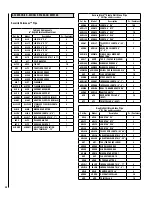
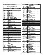
Page 22: ...ickel Olympic Leg H5620 Single Brushed Gold Olympic Leg H5619 Single Brushed Nickel Olympic Leg 22 H5649 Heatshield Leg Fastener Kit 23 71110 Bottom Heatshield S160 and SWS160 24 H5662 Cascade Olympic Leg Kit Outside Air Plenum Box FSB BLOWER PARTS 25 H8062 FSB700 Blower Only Assembly w blower wiring harness 26 H5658 Fan Blade FSB700 27 H5657 Fan Cage FSB700 28 H8063 FSB700 Blower Only Wire Harnes...

Page 23: ...23 NOTE DIAGRAMS ILLUSTRATIONS ARE NOT TO SCALE Replacement Parts Models S160 and SWS160 ...

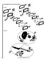
Page 24: ...24 NOTE DIAGRAMS ILLUSTRATIONS ARE NOT TO SCALE Replacement Parts Models S160 and SWS160 Door Parts Blower Parts 7 13 1 2 3 4 5 6 8 1 2 3 4 5 9 10 8 14 11 6 7 12 25 29 31 28 27 26 32 30 ...

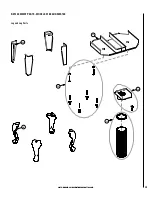
Page 25: ...25 NOTE DIAGRAMS ILLUSTRATIONS ARE NOT TO SCALE Replacement Parts Models S160 and SWS160 NOTE DIAGRAMS ILLUSTRATIONS ARE NOT TO SCALE 22 24 18 20 21 23 Leg and Leg Parts ...

Page 26: ...26 NOTE DIAGRAMS ILLUSTRATIONS ARE NOT TO SCALE Replacement Parts Models S160 and SWS160 15 18 15 18 19 16 17 19 Ash Drawer Pedestal and Pedestal ...

Page 27: ...8 LEG OLY BRN Olympic Sculptured Brushed Nickel 4 per pkg 70003 LEG CAS B Cascade Steel Black 4 per pkg HEAT SHIELD REQUIRED WITH LEGS 71110 WSHS 160 Heat Shield ref form 506033 14 FACEPLATE KITS INCLUDES FACEPLATE HANDLE AND NAMEPLATE H7901 ARCH FPK BG Arch Faceplate Brushed Gold H7902 TRAD FPK BG SM Sm Traditional Faceplate Brushed Gold H7904 ARCH FPK G Arch Faceplate Gold H7905 TRAD FPK G SM Sm...

Page 28: ...LE LENGTH 3 9 4 6DL36A 6DL36A ADJUSTABLE LENGTH 3 34 2 6DT 6DT TEE TEE CAP INCLUDED 4 6DE45 6DE45 ELBOW 45 DEGREE 4 6DE90 6DE90 ELBOW 90 DEGREE 4 6DMA 6DMA MASONRY ADAPTOR 1 6UP 6UP FLUE EXTENSION 10 6DAB 6DAB STOVE ADAPTOR 8 6DLW7 6DLW7 INCREASER LENGTH 6 7 4 6DLW8 6DLW8 INCREASER LENGTH 6 8 4 6DLK 6DLK DAMPER UNIT DL 6 4 6DQDH 6DQDH DECORATIVE COLLAR 25 6DQ 6DQ TRIM COLLAR 10 Security Chimneys P...

Page 29: ...6SSAC 6SSAC ADJUSTABLE SQUARE CATHEDRAL SUPPORT w COUPLER 1 6SFC 6SFC FINISHING SUPPORT W COUPLER 1 Cat No Model Description Pc Container Supports continued 6SM 6SM TEE SUPPORT 1 6SMA 6SMA GALVALUME ADJUSTABLE TEE SUPPORT 2 TO 6 5 SO SO OFFSET SUPPORT WALL SUP PORT 10 ST ST ROOF SUPPORT 10 6SD 6SD FLOOR SUPPORT 5 6SP 6SP ANCHOR PLATE 10 Braces and Firestops 6BF 6BF FIRESTOP 10 6RSM30 6RSM30 ANGLED...

Page 30: ...30 NOTE DIAGRAMS ILLUSTRATIONS ARE NOT TO SCALE SAFETY LISTING LABEL eNGLISH 2011 2012 2013 ...

Page 31: ...31 NOTE DIAGRAMS ILLUSTRATIONS ARE NOT TO SCALE SAFETY LISTING LABEL FRENCH ...

Page 32: ...e appliance 3 The part number 4 The description of the part 5 The quantity required 6 The installation date of the appliance If you encounter any problems or have any questions concerning the installation or application of this system please contact your dealer LENNOX HEARTH PRODUCTS 1508 Elm Hill Pike Suite 108 Nashville TN 37210 visit us at www Lennox com 1 800 9 LENNOX Product reference informa...

Reviews: