Page 4
FILTERS
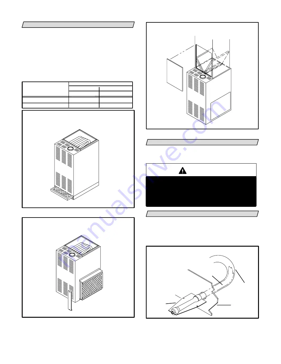
80MGF series units are equipped with external filters
which should be inspected monthly and replaced when
necessary to assure proper furnace operation. See table
1 for filter sizes. Replacement filters used with
80MGF-40/60/75 units must have a minimum velocity ratĆ
ing of 400 FPM. Replacement filters used with
80MGF-100/120/140 units require a minimum velocity
rating of 625 FPM. Figures 3, 4 and 5 show possible filter
locations.
TABLE 1
MODEL NO.
FILTER SIZE
80MGF-45/60/75
16" X 20" X 1"
UPFLOW
DOWNFLOW
16" X 20" X 1"
1 FILTER
2 FILTERS
80MGF-100/120/140
20" X 20" X 1"
16" X 20" X 1"
UPFLOW FURNACE
BOTTOM RETURN AIR
FIGURE 3
UPFLOW FURNACE
SIDE RETURN AIR
FIGURE 4
DOWNFLOW FURNACE
FILTERS IN PLENUM RACK
FIGURE 5
BLOWER
Check and clean blower wheel for any debris. Blower moĆ
tor is prelubricated for extended bearing life. No further luĆ
brication is needed.
WARNING
Blower door must be securely in place when
blower and burners are operating. Gas fumes,
which could contain carbon monoxide, can be
drawn into living space resulting in personal inĆ
jury or death.
BURNER FLAME
The 80MGF burner flame is not adjustable; however, the
flame should be inspected at the beginning of each heatĆ
ing season and burners should be cleaned, if necessary.
Burner flame should be blue when burning natural gas,
blue/yellow when burning propane gas.
BURNER FLAME
FIGURE 6
BURNER
FLAME
HEAT
EXCHANGER
TUBE
VEST
PANEL
FLAME APPEARS BLUE IF
BURNING NAT. GAS; BLUE/
YELLOW FOR PROPANE.


