# 47860A005
Page 23
Primary Limit Control
This is a normally closed control that opens if abnormally
high circulating air temperatures occur. It is an automatic
reset control.
Auxiliary Limit Control
This is a normally closed control that opens under abnor-
mal “reverse air flow” conditions that could occur in a
counterflow or horizontal installation if the circulating
blower fails. It is an automatic reset control.
Interlock (Blower Door) Switch
When the blower door is removed, the interlock switch
breaks the power supply to the burner controls and blower
motor. The switch operation must be checked to confirm it
is operating correctly.
Blower Control Board
The blower control board operates the circulating air
blower, the combustion blower and any accessories
connected to it. These models feature user-selectable
blower “off” delay times (60, 90, 120, and 180 seconds)
that are factory set to provide a 120-second blower “off”
delay on heating (see wiring diagram on page 27).
Refer to the furnace wiring diagram while using the
following procedure to change motor speed:
1. Turn off electrical power to the unit.
2. Connect the desired speed tap for cooling on the
blower control board.
3. For heating speed, check the temperature rise and, if
necessary, adjust the blower speed tap to maintain
temperature rise within the range shown on the
furnace rating plate.
To use the same speed tap for both heating and
cooling, install a piggyback terminal on the speed tap
using a short jumper. Wire 1/4" quick connect termi-
nals on both ends to jumper the “HEAT” and “COOL”
speed on the blower control board.
4. The remaining speed taps must be connected to
dummy terminals marked “PARK” on the blower
control board.
Checking and Adjusting Gas Input
The minimum permissible gas supply pressure for the
purpose of input adjustment is 5" W.C. for natural gas and
11" W.C. for propane gas. This furnace requires conversion
for use with propane (see
Accessories
section on page 26
for correct kit). The maximum inlet gas supply pressure is
10.5" W.C. for natural gas and 13" W.C. for propane.
Gas input must never exceed the value shown on the
furnace rating plate. The furnace is equipped for rated
input at manifold pressures of 3.5" W.C. for natural gas or
10.0" W.C. for propane gas.
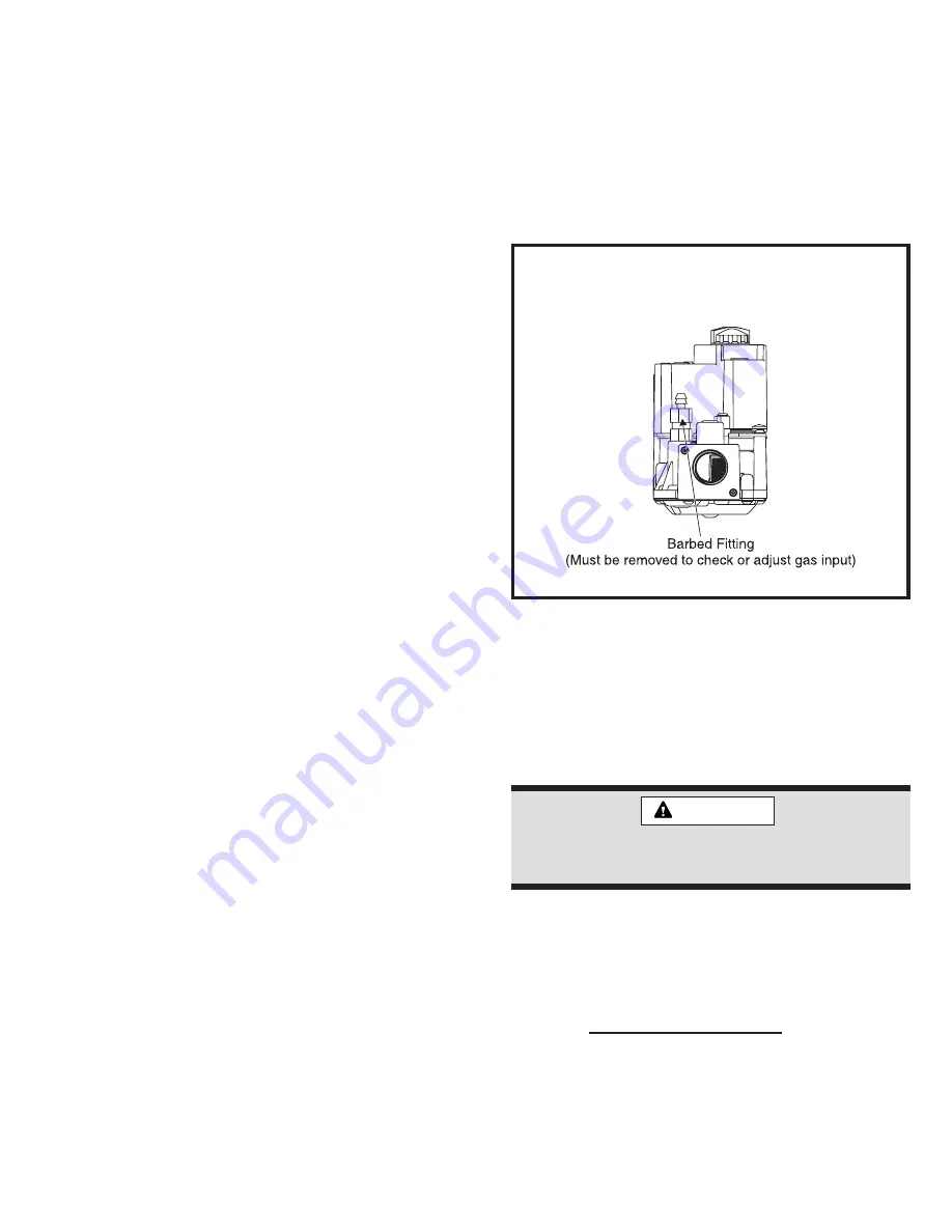
To measure the manifold pressure, disconnect the hose
and remove the barbed fitting in the downstream side of
the gas valve and connect a water manometer or gauge
(see Figure 33).
To adjust the regulator, turn the adjusting screw(s) on the
regulator clockwise to increase pressure and input; coun-
terclockwise to decrease pressure and input.
Replace the barbed fitting and reconnect the hose after
measuring and/or adjusting the regulator.
Figure 33
Checking and Adjusting
Gas Input
For Natural Gas:
Check the furnace rate by observing
the gas meter, when available, making sure all other gas
appliances are turned off. The test hand on the meter
should be timed for at least one revolution. Note the
number of seconds for one revolution.
x
3600 x
= Cubic Feet Per Revolution
BTU/HR
INPUT
# Seconds Per Revolution
Heating
Value
The heating value of the gas can be obtained from the local
utility company.
For Propane Gas:
The only check for the furnace rate is to
properly adjust the manifold pressure using a manometer
The furnace rate must be /- 2% of the
appliance rating input.
CAUTION


