11
Desired temperature (Set Point) =23ºC
R4=0,5ºC
R3=2ºC
R3=2ºC
R4=0,5ºC
R9=2ºC
R8=4ºC
22,5ºC
23,5ºC
20,5ºC
18,5ºC
25,5ºC
Electrical
heater
Compressor
Unit is working on cooling mode
ON
ON
OFF
OFF
OFF
ON
compressor
Unit is working on heating mode
E2
E1
C2
C1
C1
C2
The unit has automatic sequence
change, therefore the compressors
turn on or turn off depending on
which one has been more time
operating or stand-by.
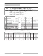
HOW REGULATION PARAMETERS WORK ? :
Through R3, R4, R8, R9 parameters we set the temperatures for which compressor and electrical heater will turn on,
as figure shows:
MODIFICATION OF SET POINT VALUE
To modify the set-point value, see page 5 on this manual.
PROGRAMMING THE PARAMETERS
COD
MIN MAX UNIT VAR. DEF
DESCRIPTION
C7
0
Khrs
---
Hour-counter compressor 1. It indicates the number of compressor operating hours.
Hour-counter compressor 2. It indicates the number of compressor operating hours.
When 19.900 working hours have been reached, the parameter starts counting
again.
19.9
F4
0
0.1
0
Supply fan operating hours threshold. It establishes the number of indoor fan
operating hours beyond which the maintenance intervention signal (alarm thf)
is activated.
F4= 0 : disables this function, alarm will not be visualized.
F4=values from 1 to 10: number of hours x 1000 of indoor fan operating hours.
10.0
---
H7
1
2
---
---
1
It establishes what is displayed on the field in the top right of the display:
H7= 1 Shows the value of the current set-point.
H7= 2 Shows outdoor coil and otudoor temperature ( free cooling option).
VALUES
F3
0
Khrs
---
Hour-counter inner fan. It indicates the number of inner fan operating hours.
When 19.900 working hours have been reached, the parameter starts counting
again.
19.9
---
---
H9
0
1
0
Only for terminal with clock function (as an option).
It establishes the display format:
H9 =0 THE FORMAT IS 24 HOUR CLOCK
H9 =1 THE FORMAT IS 12 HOUR CLOCK
1
---
C5
C6
0
Khrs
0.1
Compressor hour counter maintenance threshold establishes the number of
compressor operating hours beyond which the maintenance intervention messages
HR1- HR2 are activated.
C7=0 disables this function.
10.0
---
Parameters F3/F4 allow setting a number of inner fan operating hours after which the display shows the alarm code
thf, which means air filter should be changed or cleaned.
Therefore, parameter F4 should be changed, establishing the number of fan operating hours X1000 beyond which
the maintenance signal thf is activated.
Format 24 hours
Format 12 hours
aut
set
PM
aut
set
Ambient
temperature
Outdoor coil temperature
or
Outdoor temperature


