background image

13

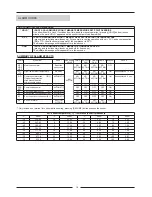
ALARM CODES

TERMINAL

The detection of an alarm brings the display of the alarm code and the letters “AL”, alternating with the  display

of the temperature.

When more than one alarm is detected at the same time, the display automatically scrolls through the

occurred alarms.

CODE

SIGNAL
DESCRIPTION

EFFECT
RESET

HR F

Supply fan maintenance alarm (filter clean)

When the indoor unit fan has exceeded the number of operating hours specified by parameter F4 (factory setting F4=0)

the maintenance message HR F is displayed
Only alarm indication, unit does not stop
To reset, the operating hour-counter must be set to zero parameter F3

Press [SET] + [HOLD] buttons

The display shows parameter values

Using the   buttons get the parameter F3

Press [SET] button to confirm and with the   buttons change the value to 0

CODE

SIGNAL
DESCRIPTION
EFFECT

RESET

HI T

High temperature alarm

Indoor temperature has rise above 32ºC during 10 minutes
Only alarm indication, unit does not stop

Unit would operate on these conditions only for short periods of time

Press RESUME button for more than 5 seconds

CHECK POINTS - Sensor values (relationship temperature-resistance), sensor position, and air distribution.

- Check parameter S4 (factory setting S4=0).

  S4= allow the correction of the value measured by ambient temperature sensor.

CODE

SIGNAL
DESCRIPTION
EFFECT

RESET

LO T

Low temperature alarm

Indoor temperature has falls bellow 10ºC during 10 minutes
Only alarm indication, unit does not stop

Unit would operate on these conditions only for short periods of time

Press RESUME button for more than 5 seconds

CHECK POINTS - Sensor values (relationship temperature-resistance), sensor position, and air distribution.

- Check parameter S4 (factory setting S4=0).

  S4= allow the correction of the value measured by ambient temperature sensor.

CODE

SIGNAL

DESCRIPTION
EFFECT
RESET

th F

External alarm from indoor fan internal protection open:

COMPACTAIR (F15)  / COMPACTAIR 100D (F17)

AIRCOOLAIR (F15)  / AIRCOOLAIR From 100D (F37)

When digital input ID1 is opened the alarm message th F is displayed
Alarm indication and all the outputs are switched off

Press RESUME button for more than 5 seconds when the cause that generated the alarm is reset

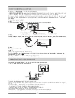
CHECK POINTS 1. Power board operation:

- Do a shortcut connection between GND and ID1 on pcb. With this action a by pass for the protection line is done.

- If the alarm disappears and the control operates, the problem must be the protection components (go to point 2).


è

 If the alarm does not disappear, power board is defective.

2. Check continuity, loose connections and verify that indoor fan motor operating current is within values..

When the unit is on mode OFF, sensor alarms are detected only.

POWER BOARD

On centre of power board is located 

jumper J3, 

which should be in position

 1-2 (INT - ID COM)

The power board also features a signalling 

green LED

, which provides information:

   - 1 flash 

every 3 seconds: normal operation.

   - 2 flashes 

every


3 seconds: serial communication error (ALARM CODE 

EST

); the power board is not receiving the data sent by

the terminal.

   - 3 flashes 

every


3 seconds: serial communication error (ALARM CODE 

ESR

); the terminal is not receiving the data sent by the

power board.

CODE

SIGNAL
DESCRIPTION

EFFECT
RESET

HR 1 – HR 2

Compressor 1 and 2 maintenance alarm

When the compressor has exceeded the number of operating hours specified by parameter C7 (factory setting C7=0)

the maintenance message HR 1 - HR 2 is displayed.
Only alarm indication, unit does not stop
To reset, the operating hour-counter must be set to zero parameter C5 / C6

Press [SET] + [HOLD] buttons

The display shows parameter values

Using the   buttons get the parameter C5 / C6 (compressor 1 / compressor 2)

Press [SET] button to confirm and with the   buttons change the value to 0

Summary of Contents for CLIMATIC 10 A122C-A123H

Page 1: ...Providing indoor climate comfort CLIMATIC 10 A122C A123H MUL27E 0701 09 2006 User manual Control ...

Page 2: ...CE DESCRIPTION SELECTING UNIT OPERATING MODE AND SET POINT SELECTING THE TEMPERATURE SET POINT CATEGORY CLOCK AND TIME BANDS AS AN OPTION PARAMETERS STATUS AND READINGS PROGRAMMING DEFROST MANAGEMENT POWER BOARD OF THE SYSTEM ALARM CODES REMOTE SENSORS AS AN OPTION THERMOSTATIC FREE COOLING AS AN OPTION STANDARD GUIDELINES TO LENNOX EQUIPMENT ...

Page 3: ...ormation pertaining to your system The clearly marked buttons and informative display make it extremely easy to understand and simple to use Please take a few moments to read the brief instructions and familiarize yourself with the various functions in order to obtain maximum benefit from this truly unique electronic control Since this type of control panel is factory configured for each applicati...

Page 4: ...nstalled in the room Electrical panel in the unit Power board AIR CONDITIONING UNIT Two lead shielded cable with a cross section of 1mm 2 When making the connection to the power board special attention must be paid to the polarity the T terminal must be connected to the T terminal on the power board similarly for the T terminal in case the cables are connected in the opposite order the instrument ...

Page 5: ...ll show up the set point where room temperature was showed before Pressing simultaneously the front buttons the display will show up the software version for five seconds SIDE BUTTONS These buttons allow access to all the other functions of the control Indicates change value of parameters THE CONTROL IS ACTIVE 5 SECONDS FROM THE TIME UNIT IS ELECTRICALLY SUPPLIED Time band indication Probe measure...

Page 6: ...rking the symbol will appear on the display AUTO The system automatically switches from cooling to heating mode depending on the position of the ambient temperature in respect to the set point FAN The unit will work on fan mode when fan is working the symbol will appear OFF The thermostat does not perform the regulation the symbol appear on the display To be able to select a fan operating mode coo...

Page 7: ...bol The room is occupied yet a lower level of comfort is required SELECTING THE TEMPERATURE SET POINT CATEGORY How to change the desired temperature set point for the different categories Pressing the SET button in manual operating mode selects comfort category During the time the symbol is flashing pressing the front buttons and changes the currently set point used by the control This is the set ...

Page 8: ...t different times for each day of the week and at different set points yet they must be chosen from the three categories previously programmed EXAMPLE The table below shows an example of time bands clock for a week 1º Set the actual time to make once when terminal is installed for the first time Press clock The days are scrolled using the front buttons Press clock to accept Mo t1 t2 t3 t4 t5 t6 Mo...

Page 9: ...m 12 to 7 o clock is indicated as follows Pressing front buttons Stops the programming for that day and let you start programming for another day Set the program start day with the front buttons and press clock to accept 1 3 4 2 PROGRAMMING PROCESS Mo Tu We Th Fr Sa Su Mo Tu We Th Fr Sa Su Mo Tu We Th Fr Sa Su Set the set point category for the band with the front buttons while flashing press cloc...

Page 10: ...e front buttons Shows the time band during the set point will be set The desired set point can be changed using the front buttons and will maintain the change for three hours Press resume button to return to time band operation before the three hours elapse A Change the desired set point of the current time band during three hours HRS The set point will remain until resume button is pressed to ret...

Page 11: ... Khrs hoursx1000 VAR Minimum variation allowed DEF The default value factory set The table below gives the following information for each parameter The parameters are scrolled using the front buttons The modifications are accepted by pressing set again clock set mode fan hold resume clock set mode fan hold resume clock set mode fan hold resume R3 2 0 20 C 0 5 2 Temperature differential cool heat R...

Page 12: ...ctivated F4 0 disables this function alarm will not be visualized F4 values from 1 to 10 number of hours x 1000 of indoor fan operating hours 10 0 H7 1 2 1 It establishes what is displayed on the field in the top right of the display H7 1 Shows the value of the current set point H7 2 Shows outdoor coil and otudoor temperature free cooling option VALUES F3 0 Khrs Hour counter inner fan It indicates...

Page 13: ...n START DEFROST CYCLE The defrost cycle begins when outdoor probe temperature reaches 3ºC END DEFROST CYCLE The defrost cycle ends when outdoor probe temperature reaches 25ºC DELAY BETWEEN TWO DEFROST REQUESTS The time between 2 defrost cycles will be calculated between the end of one and the beginning of the other and it will be between 14 and 35 minutes depending on external conditions The defro...

Page 14: ...sured by ambient temperature sensor CODE SIGNAL DESCRIPTION EFFECT RESET th F External alarm from indoor fan internal protection open COMPACTAIR F15 COMPACTAIR 100D F17 AIRCOOLAIR F15 AIRCOOLAIR From 100D F37 When digital input ID1 is opened the alarm message th F is displayed Alarm indication and all the outputs are switched off Press RESUME button for more than 5 seconds when the cause that gene...

Page 15: ...istance 4500 Ohms 10 Reset resistance 2750 Ohms 10 Module time delay 30 minutes 10 Compressor protector module is based on the temperature resistance of thermistor chain five PTC resistances one thermistor for each phase NAT 80ºC on winding upper side the fourth thermistor on winding lower side NAT 140ºC and the fifth thermistor in the discharge port NAT 140ºC Operating description 3 Check outdoor...

Page 16: ...tly CHECK POINTS Measure relationship temperature resistance check for possible loose connection cable breakage CODE SIGNAL DESCRIPTION EFFECT RESET E SR Terminal communication error Error in the serial communication between terminal and power board terminal does not receive data from power board The LED on the power board blinks 3 times in 3 seconds normal operation 1 blink every 3 seconds Alarm ...

Page 17: ...hm 329 20 247 50 188 40 144 00 111 30 86 39 67 74 53 39 C 30 35 40 45 50 55 60 65 Kohm 8 31 6 94 5 82 4 91 4 16 3 53 3 02 2 58 ºC 10 5 0 5 10 15 20 25 Kohm 42 25 33 89 27 28 22 05 17 96 14 68 12 09 10 00 ºC 70 75 80 85 90 95 100 105 Kohm 2 22 1 92 1 66 1 45 1 26 1 10 0 97 0 85 SUMMARY OF ALARM EFFECTS CODE HR 1 HR 2 HR F HI T LO T E ID th F E SR E ST E1 E2 E3 EE MEANING Maintenance alarm High low ...

Page 18: ...ture For these conditions air intake gate is opened Two thermostats on the air discharge are incorporated for the safety of the unit One of them for 4ºC closes the gate in order to prevent freezing The other one for 10ºC opens the gate to take advantage from outside air These thermostats only work when the free cooling is enabled Programming option is included on it You can connect as an option re...

Page 19: ...ating instructions contain useful and important information for the smooth operation and maintenance of your equipment The instructions also include guidelines on how to avoid accidents and serious damage before commissioning the equipment and during its operation and how to ensure smooth and fault free operation Read the operating instructions carefully before starting the equipment familiarise y...

Page 20: ...om BELGIUM LUXEMBOURG CZECH REPUBLIC FRANCE GERMANY GREAT BRITAIN IRELAND NETHERLANDS POLAND PORTUGAL RUSSIA SLOVAKIA SPAIN UKRAINE OTHER COUNTRIES Due to Lennox s ongoing commitment to quality the Specifications Ratings and Dimensions are subject to change without notice and without incurring liability Improper installation adjustment alteration service or maintenance can cause property damage or...

Reviews: