background image

TECHNICAL DATA 

USING OF THE INTERFACE KP06 FOR ECOLEAN UNITS


8/13  


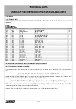
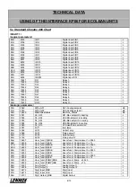
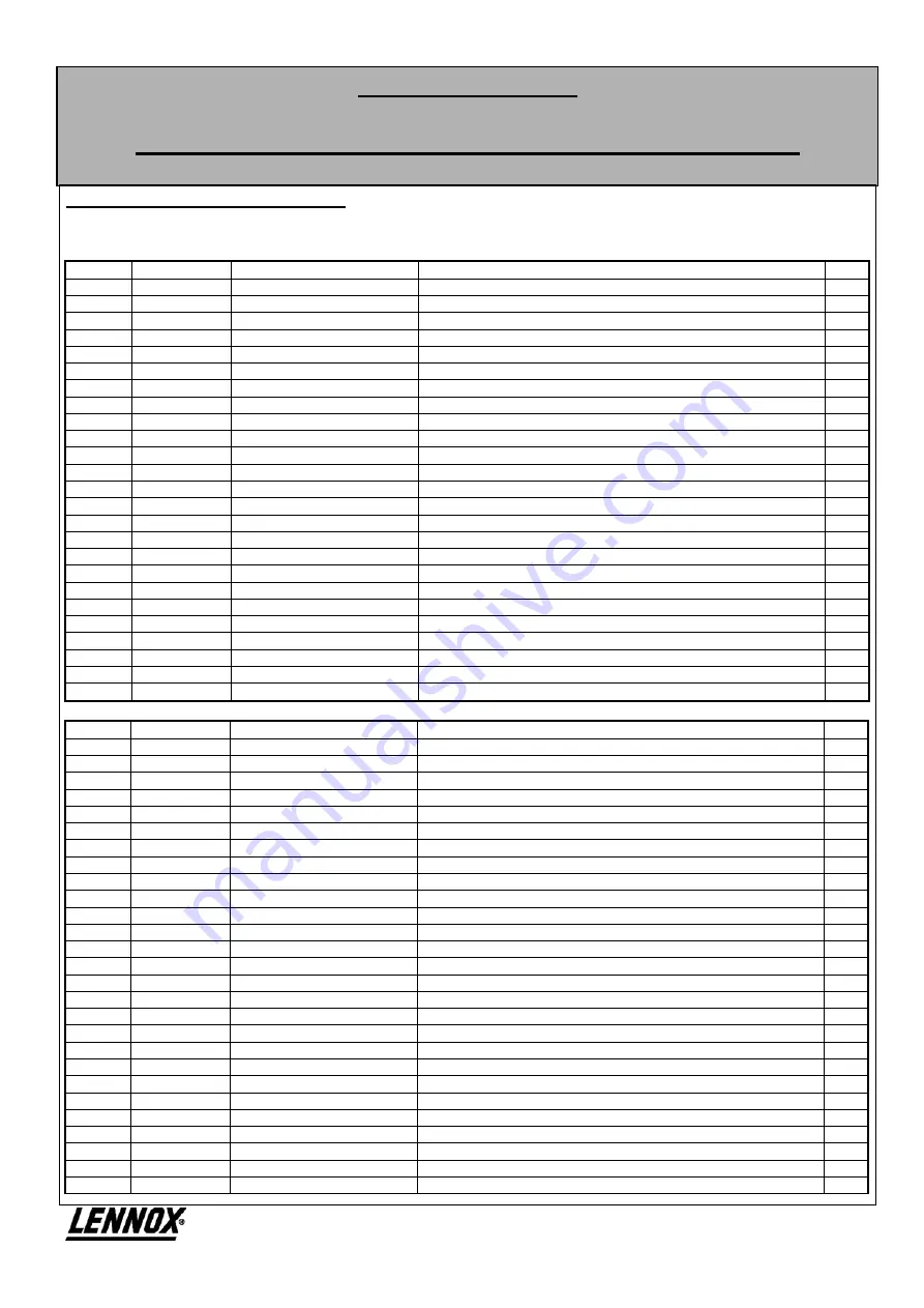
5.c Standard Climatic 400 Chart


/CHART 1/ 
/Logical parameters/ 

80H 

8193 

I/ID1 

Digital input I/ID1:  

81H 

8194 

I/ID2 

Digital input I/ID2:  

82H 

8195 

I/ID3 

Digital input I/ID3:  

83H 

8196 

I/ID4 

Digital input I/ID4:  

84H 

8197 

I/ID5 

Digital input I/ID5:  

85H 

8198 

I/ID6 

Digital input I/ID6:  

86H 

8199 

I/ID7 

Digital input I/ID7:  

87H 

8200 

I/ID8 

Digital input I/ID8:  

88H 

8201 

I/ID9 

Digital input I/ID9:  

89H 

8202 

I/ID10 

Digital input I/ID10:  

8AH 

8203 

I/ID11 

Digital input I/ID11:  

8BH 

8204 

I/ID12 

Digital input I/ID12:  

8CH 

8205 

I/ID13 

Digital input I/ID13:  

8DH 

8206 

I/ID14 

Digital input I/ID14: 

8EH 

8207 

I/ID15 

Digital input I/ID15:  

8FH 

8208 

I/IDST4 

Digital input ST4:  

90H 

10241 

RL1 

Relay1 -  

91H 

10242 

RL2 

Relay2 -  

92H 

10243 

RL3 

Relay3 -  

93H 

10244 

RL4 

Relay4 -  

94H 

10245 

RL5 

Relay5 -  

95H 

10246 

RL6 

Relay6 -  

96H 10247 

RL7 

Relay7 

97H 10248 

RL8 

Relay8 

98H 

10249 

RL9 

Relay9 -  

99H 

10250 

RL10 

Relay10 -  

/Analogic parameters/ 

00H 2049 

M/Pa_G01 

G01-Cooling setpoint 

L/E 

01H 2050 

M/Pa_G02 

G02-Heating setpoint 

L/E 

02H 16495 

M/MachineStatus 

Machine_Status 

L/E 

80H 

2051 

Pa_H01 

H01-Max setpoint in heating 

81H 

2052 

Pa_H02 

H02-Min setpoint in heating 

82H 

2053 

Pa_H03 

H03-Max setpoint in cooling 

83H 

2054 

Pa_H04 

H04-Min setpoint in cooling 

84H 2060 

Pa_H10 

H10-HeatPump 

selecction 

85H 

4097 

I/ST1 

Inlet temp  

86H 

4098 

I/ST2 

Outlet Temp  

87H 

4099 

I/ST3 

Piping circuit 1 

88H 4100 

I/ST4 

Outdoor 

temp 

89H 

4102 

I/ST6 

Piping circuit 2 

8AH 

16497 

Hour_funct,[1]MSB 

Hours funct. Compresseur 1 x 256 h 

8BH 

16498 

Hour_funct,[1]LSB 

Hours funct. Compresseur 1 x 1h 

8CH 

16499 

Hour_funct,[2]MSB 

Hours funct. Compresseur 2 x 256 h 

8DH 

16500 

Hour_funct,[2]LSB 

Hours funct. Compresseur 2 x 1h 

8EH 

16501 

Hour_funct,[3]MSB 

Hours funct. Compresseur 3 x 256 h 

8FH 

16502 

Hour_funct,[3]LSB 

Hours funct. Compresseur 3 x 1h 

90H 

16503 

Hour_funct,[4]MSB 

Hours funct. Compresseur 4 x 256 h 

91H 

16504 

Hour_funct,[4]LSB 

Hours funct. Compresseur 4 x 1h 

92H 

16505 

Hour_funct,[PUMP]MSB 

Hours funct. Pump   x 256 h 

93H 

16506 

Hour_funct,[PUMP]LSB 

Hours funct. Pump   x 1h 

94H 14337 

Ana_Output_1 

Analog Output 1 

95H 14338 

Ana_Output_2 

Analog Output 2 

96H 16473 

Digit_Input_MSB Digit_Input 

97H 16474 

Digit_Input_LSB Digit_Input 

98H 16731 

Digit_Output_MSB 

Digital Output 

Summary of Contents for ECOLEAN KP06

Page 1: ...Providing indoor climate comfort JBUS BMS INTERFACE ECOLEAN MUL33E 0904 09 2006 User manual ...

Page 2: ......

Page 3: ...ing heating setpoint Read the limitations in the unit as the functioning of the heat pump the maximum setpoint and minimum setpoint Read all the alarm status Read inlet water temperature outlet water temperature condensing temperature and outdoor temperature this last one only if the unit is fitted with the dynamic setpoint option Read inlet signals status pressostats water flow switch thermal rel...

Page 4: ...g local normatives Every KP06 have to be supplied with 230 Vac 50 Hz PE 15 Use a cable with a 1 5 mm2 section Maximum length of the RS485 net from the BMS system to the last is 1 000 m BMS connection is RS 485 It has to be connected to the port RS 485 of BMS with every KP06 in parallel It is advisable to use screened cable with a 0 5 mm2 for this type of connection Jumpers J8 y J9 of the connected...

Page 5: ...lus metallic screen 20 AWG nominal capacity between cables of 89 pF nominal capacity between a cable and the metallic screen of 161 pF Use the cables to connect and and the screen to connect GND In each Bus Adapter of the last Ecolean connect a 120 ohms resistance 1 4w between and Each Ecolean unit connected to a KP06 has a different address between 1 and 8 This address is introduced in the contro...

Page 6: ...Digit_Input L 8FH 16469 Digit_Output Digital Output L 90H 16492 Alarm_Auto_1 Alarm_Auto_1 L 91H 16493 Alarm_Auto_2 Alarm_Auto_2 L 92H 16494 Alarm_Auto_3 Alarm_Auto_3 L 93H 16495 Alarm_Manu_1 Alarm_Manu_1 L 94H 16496 Alarm_Manu_2 Alarm_Manu_2 L 95H 16497 Alarm_Manu_3 Alarm_Manu_3 L 96H 18433 Version VERSION L 5 b Detailed information about CLIMATIC 200 parameters 00H 01H parameters readable and wri...

Page 7: ...ly readable Shows a 0 value if the unit is cooling only and a 1 value if the unit is heat pump Use these value to establish if it is posible to modif The heating setpoint H01 parameter and it is more important to know if it can be switched in heat pump mode H02 parameter 85H 86H 87H 88H 89H 8AH 8BH 8CH parameters only readable In this parameters we can read the values measured by different tempera...

Page 8: ...t 7 Bit 6 Bit 5 Bit 4 Bit 3 Bit 2 Bit 1 Bit 0 Low pressure switch High pressure switch Remote ON OFF Compressor 1 protection Flow switch Not used Not used Compressor protection 2 Example in one unit EAC 0431 the value of 208 1101 0000 in binary system shows that the compressor protection the high pressure switch and the low pressure switch are closed and that the remote ON OFF plus the flow switch...

Page 9: ...rload relay E04 Fan overload relay E05 Antifreeze E06 Error in outlet water sensor E07 Error in refrigerant piping sensor E11 Piping high temperature E12 Piping low temperature E40 Error in inlet water sensor E41 Error in flow switch sensor E42 Error in outdoor temperature sensor E43 External antifreeze E44 Unit without charge E45 Configuration error E46 High inlet water temperature Some of these ...

Page 10: ...ing setpoint L E 02H 16495 M MachineStatus Machine_Status L E 80H 2051 Pa_H01 H01 Max setpoint in heating L 81H 2052 Pa_H02 H02 Min setpoint in heating L 82H 2053 Pa_H03 H03 Max setpoint in cooling L 83H 2054 Pa_H04 H04 Min setpoint in cooling L 84H 2060 Pa_H10 H10 HeatPump selecction L 85H 4097 I ST1 Inlet temp L 86H 4098 I ST2 Outlet Temp L 87H 4099 I ST3 Piping circuit 1 L 88H 4100 I ST4 Outdoo...

Page 11: ...5H 96H 97H Compressor 1 4 way valve 1 Compressor 2 4 way valve 2 Water pump Electrical heater Electrical heater Alarm 98H 99H Not used Not used EAC 1003 to 1303 80H 81H 82H 83H 84H 85H 86H 87H High pressure switch Low pressure switch 1 Fan protection 1 Defrosting pressostat 1 Flow switch High pressure switch 2 Low pressure switch 2 Fan protection 2 88H 89H 8AH 8BH 8CH 8DH 8EH 8FH Defrosting presso...

Page 12: ...d heating setpoint 43 0ºC 02H parameter readable and writable This parameter defines the function of the unit as following Parameter 02H 00H Stopped unit Parameter 02H 80H Stand By mode Parameter 02H 81H Cooling only mode Parameter 02H 82H Heat pump mode Important If different values are used the result obtained maybe wrong To know if the unit can work in heat pump mode read the value of the 84 H ...

Page 13: ...sor 2 LSB 8EH Hours of functioning of compressor 3 MSB 8FH Hours of functioning of compressor 3 LSB 90H Hours of functioning of compressor 4 MSB 91H Hours of functioning of compressor 4 LSB 92H Hours of functioning of water pump MSB 93H Hours of functioning of water pump LSB To calculate the value the following formula has to be taken into account HR MSB 256 LSB Example in 8AH we can read the valu...

Page 14: ... Fan protection 2 Remote ON OFF Compressor protection 2 Low pressure switch 2 Flow switch Defrost swicth 1 High pressure switch 2 Example in a unit EAC 1103 the value of 96H is 208 1111 1010 in binary shows that the protections of the compressors 4 3 and 2 the protection of the fan 1 the high pressure switch 1 and the low pressure switch 1 are closed 98H y 99H will show the functioning of the foll...

Page 15: ... pressure piping circuit 1 E13 Overload protection compressor 2 E19 High pressure compressor 2 E21 High pressure circuit 2 E22 Low pressure circuit 2 E23 Overload protection compressor3 E24 Fan overload protection 2 E25 Antifreeze protection 2 E26 Error sensor ST5 E27 Error refrigerant piping sensor 2 E29 High pressure compressor 3 E31 High piping temperature circuit 2 E32 Low piping temperature c...

Page 16: ......

Page 17: ...0904 09 2006 BELGIUM LUXEMBOURG CZECH REPUBLIC FRANCE GERMANY NETHERLANDS POLAND PORTUGAL RUSSIA SLOVAKIA SPAIN UKRAINE UNITED KINGDOM AND IRELAND OTHER COUNTRIES Due to Lennox s ongoing commitment to quality the Specifications Ratings and Dimensions are subject to change without notice and without incurring liability Improper installation adjustment alteration service or maintenance can cause pro...

Reviews: