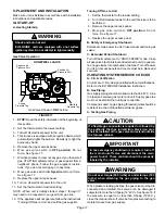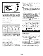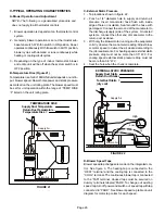
background image

Page 14

13. Blower Motor

IMPORTANT

Each blower is statically and dynamically bal­
anced as an assembly before installation in the
unit.

EL180UHNE units are equipped with a constant torque

ECM motor.  It has a DC motor coupled to an electronic con­

trol module both contained in the same motor housing.  The

motor is programmed to provide constant torque at each of

the five selectable speed taps. Each tap requires 24 volts to

energize.

Input Voltage Requirements

The circuit is designed to be operated with AC voltage. To

enable a tap requires 12 to 33VAC. Expected current draw

will be less than 20mA.

Troubleshooting the Motor

Troubleshooting the motor is an easy process. Follow

steps below.

 1-  Shut off power to unit.

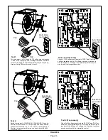
 2-  Remove input plugs P48 and P49 from motor. See

figure 12 for troubleshooting procedure.

If correct voltage is present in tests 1 and 2 and motor is not

operating properly, replace motor. The motor is not field re­

pairable.

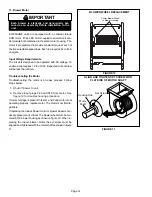
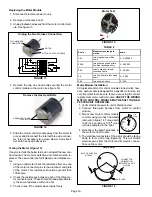
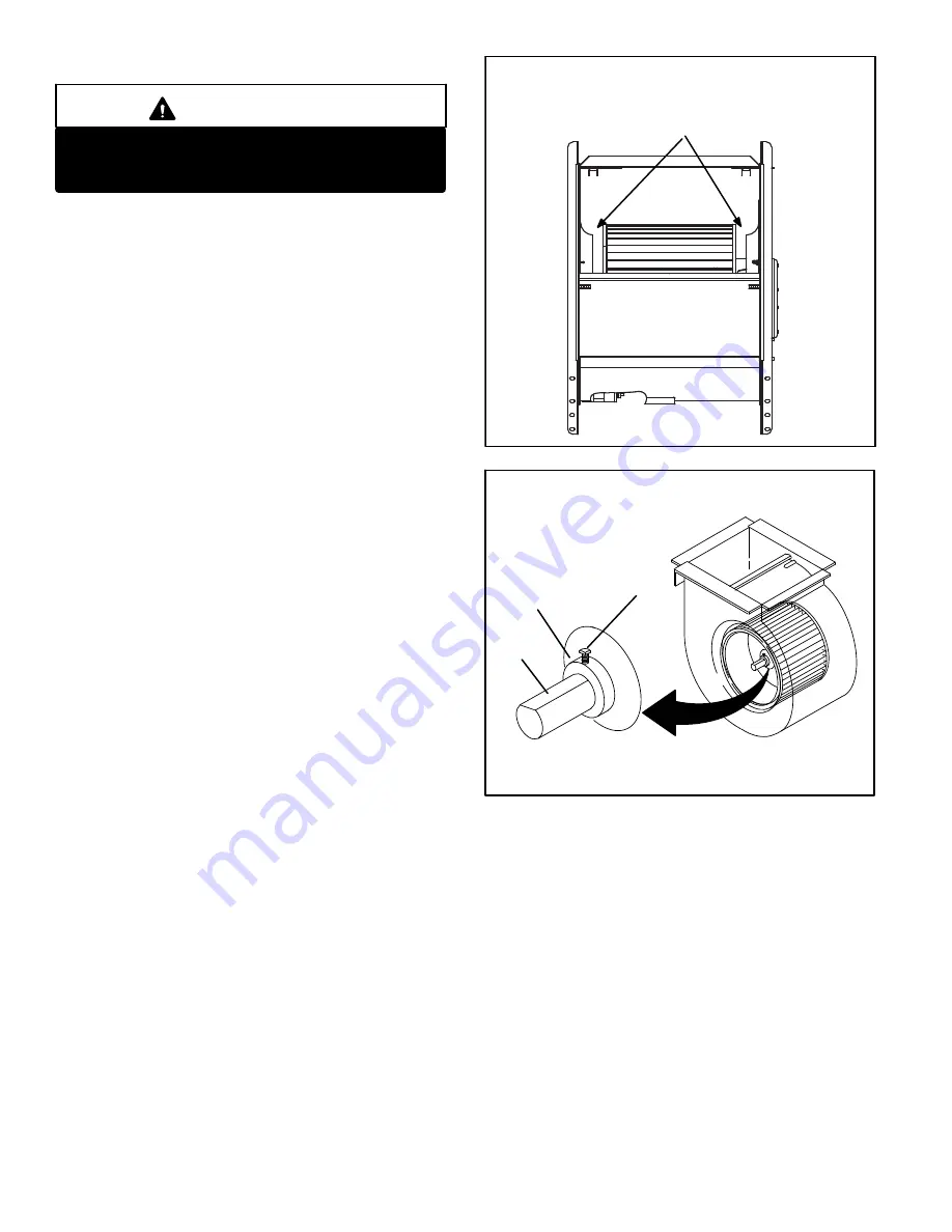
If replacing the indoor blower motor or blower wheel is nec­

essary, placement is critical. The blower wheel must be cen­

tered in the blower housing as shown in figure 10. When re­

placing the indoor blower motor the set screw must be

aligned and tightened with the motor shaft as shown in figure

11.

FIGURE 10

Center Blower Wheel

in Blower Housing

BLOWER WHEEL REPLACEMENT

FIGURE 11

Set Screw

Housing Hub

ALIGN AND TIGHTEN SET SCREW WITH

FLAT SIDE OF MOTOR SHAFT

Motor

Shaft

Summary of Contents for EL180UH040NE36A

Page 1: ...f local or state codes the guidelines and procedures outlined in this manual except where noted are recommended only and do not constitute code CAUTION As with any mechanical equipment contact with sh...

Page 2: ...ta lbs 1 package 100 113 125 149 NOTE Filters and provisions for mounting are not furnished and must be field provided 1 Annual Fuel Utilization Efficiency based on DOE test procedures and according t...

Page 3: ...3 1190 141 1030 86 930 73 835 55 0 10 1380 251 1165 150 990 95 890 89 790 65 0 20 1360 264 1115 158 950 99 840 78 730 68 0 30 1315 278 1090 171 910 110 790 89 660 61 0 40 1295 290 1070 182 865 122 740...

Page 4: ...5 220 1425 160 2235 595 1945 382 1725 262 1590 202 1430 165 0 10 2175 639 1910 427 1685 287 1545 234 1400 176 2205 611 1915 397 1695 280 1550 218 1400 193 0 20 2145 658 1885 449 1635 309 1490 246 1325...

Page 5: ...ludes integrated control interlock switch and transformer Blower Assembly Power Choke 4 and 5 Ton Only PARTS ARRANGEMENT Heat Exchanger Combustion Air Inducer Gas Valve Intake Air Elbow Access Panel I...

Page 6: ...system consisting of an in tegrated control figure 3 with control terminal designa tions in tables 1 2 and 3 sensor and ignitor figure 6 The integrated control and ignitor work in combination to en su...

Page 7: ...e Switch In 11 Rollout Switch In 12 Gas Valve Out TABLE 3 1 4 QUICK CONNECT TERMINALS 120HUM Humidifier 120VAC LINE 120VAC XFMR Transformer 120VAC CIRC Indoor blower 120VAC EAC Indoor air quality acce...

Page 8: ...Open or Watchguard Mode Limit Switch Open longer than 3 minutes 8 Rollout Switch Open 9 Pressure Switch failed to close or opened during heat demand 10 Watchguard Pressure Switch opened 5 times durin...

Page 9: ...air temperature once the heat demand is satisfied Note the supply air temperature at the instant the blower is de energized Adjust the fan off delay to achieve a supply air temperature between 90 110...

Page 10: ...h unit model number See Lennox Repair Parts Handbook if limit switch must be replaced 7 Gas Valve Figure 6 The valve is internally redundant to assure safety shut off If the gas valve must be replaced...

Page 11: ...ry make note of the tubing connections to the gas valve See figure 8 NOTE The switch is factory set and is not field adjustable It is a safety shut down control in the furnace and must not be by passe...

Page 12: ...Page 12 FIGURE 8 Replacing the Pressure Switch or Tubing...

Page 13: ...s correct then then there is a problem with the wiring between the jack plug and control If the reading is not correct the issue is the ignitor Meter set to ohms Test 3 Insert meter probes into the te...

Page 14: ...shooting the Motor Troubleshooting the motor is an easy process Follow steps below 1 Shut off power to unit 2 Remove input plugs P48 and P49 from motor See figure 12 for troubleshooting procedure If c...

Page 15: ...s fan 1 2 3 4 or 5 on input plug P49 If 24 volts is not present problem may be up stream of plug P49 Proceed to test 4 Multi Meter set to VAC 12 0 12 0 24 Multi Meter set to VAC Check for 24 volts acr...

Page 16: ...read approximate ly the same resistance within an ohm 3 Check to see if the blower wheel spins freely FIGURE 15 Motor Test TABLE 8 Scale Measurement range in words ohms 2 M two megohm two million ohm...

Page 17: ...it if service is to be performed 3 Remove the upper access panel 4 Move gas valve switch to OFF position Do not force See figure 17 5 Replace the upper access panel B Safety or Emergency Shutdown Disc...

Page 18: ...he supply pressure tap See figure 16 Loosen the screw and connect a manometer to measure supply pressure See table10 for supply line pressure Tighten screw after measurements have been taken Manifold...

Page 19: ...s a poor or partial ground Compare the readings to the table below If the read ings exceed the maximum shown in table 12 make re pairs before operating the furnace 2 In addition measure the AC voltage...

Page 20: ...ply and return air plenums Insert manometer hose flush with inside edge of hole or insulation Seal around the hose with permagum Connect the zero end of the manometer to the discharge supply side of t...

Page 21: ...X 1 1 16 X 25 X 1 1 C 21 16 X 25 X 1 1 20 X 25 X 1 1 6 Evaluate the heat exchanger integrity by inspecting the heat exchanger per the AHRI heat exchanger inspec tion procedure This procedure can be v...

Page 22: ...gn matter Remove any blockage Figure 23 shows burner detail Replace gasket between burner plate and air fuel plenum then re install burner plate 10 To clean the combustion air inducer visually inspect...

Page 23: ...BLY HEAT EXCHANGER REMOVAL FIGURE 23 Gas Valve Air Intake Assembly leave intact Heat Exchanger Air Gas Plenum Gasket Burner Burner Box Liner leave intact FIGURE 24 Remove 5 screws if necessary either...

Page 24: ...ue 5 A92 integrated control energizes B6 combustion air inducer S18 combustion air pressure switch closes Once S18 closes a 15 second pre purge follows 6 A92 integrated control energizes R33 ignitor A...

Page 25: ...rated control energizes B6 combustion air inducer S18 combustion air pressure switch closes Once S18 closes a 15 second pre purge follows 6 A92 integrated control energizes R33 ignitor A 20 second war...

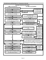
Page 26: ...VE ENERGIZED GAS VALVE OFF COMBUSTION AIR INDUCER ON INDOOR BLOWER ON HEATING SPEED LED FLASHES CODE 11 PRESSURE SWITCH CLOSED GAS VALVE OFF COMBUSTION AIR INDUCER OFF INDOOR BLOWER OFF WITH DELAY Seq...

Page 27: ...IMES FLAME SIGNAL 1 5 MICROAMPS OR GREATER YES YES YES ROLLOUT SWITCH CLOSED LED FLASHES CODE 8 ROLLOT SWITCH OPEN GAS VALVE POWER OFF COMBUSTION AIR INDUCER POWER ON INDOOR BLOWER ON SEQUENCE HOLDS U...

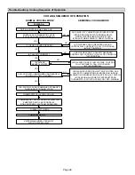
Page 28: ...OSED LED SLOW FLASH RATE REMAINS UNCHANGED THROUGHOUT COOLING CYCLE THERMOSTAT CALLS FOR COOLING COMPRESSOR CONTACTOR AND SYSTEM FAN ENERGIZED WITH 2 SECOND DELAY COOLING SPEED EAC TERM ENERGIZED COMP...

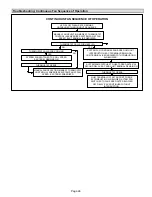
Page 29: ...FAN SWITCHED TO COOL SPEED EAC TERM REMAINS ON THERMOSTAT OPENS MANUAL FAN SELECTION MADE AT THERMOSTAT CONTROL G ENERGIZES SYSTEM FAN AT FAN SPEED EAC TERM ENERGIZED NO YES YES NO SYSTEM FAN SWITCHE...

Reviews: