Page 7
Electronic Ignition
On a call for heat the integrated control monitors the com-
bustion air inducer prove switch. The integrated control will
not begin the heating cycle if the pressure switch is closed
(by−passed). Once the pressure switch is determined to be
open, the combustion air inducer is energized. When the
differential in the pressure switch is great enough, the pres-
sure switch closes and a 15−second pre−purge begins. If
the pressure switch is not proven within 2−1/2 minutes, the
integrated control goes into Watchguard−Pressure Switch
mode for a 5−minute re−set period.
After the 15−second pre−purge period, the ignitor warms up
for 20 seconds during which the gas valve opens at 19 sec-
onds for a 4−second trial for ignition. The ignitor remains
energized for the first 3 seconds during the 4 second trial. If
ignition is not proved during the 4−second period, the inte-
grated control will try four more times with an inter purge
and warm−up time between trials of 35 seconds. After a to-
tal of five trials for ignition (including the initial trial), the inte-
grated control goes into Watchguard−Flame Failure mode.
After a 60−minute reset period, the integrated control will
begin the ignition sequence again.
The integrated control has an added feature of ignitor pow-
er regulation to maintain consistent lighting and longer igni-
tor life under all line voltage conditions.
Fan Control
Heating Fan On Delay
The heating fan on time of 30 seconds is not adjustable.
Heating Fan Off Delay
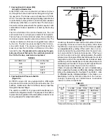
The heat fan off delay (amount of time that the blower oper-
ates after the heat demand has been satisfied) may be ad-
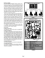
justed by changing the jumper position across the five pins
on the integrated control. The unit is shipped with a factory
fan off setting of 90 seconds. The fan off delay affects com-
fort and is adjustable to satisfy individual applications. Ad-
just the fan off delay to achieve a supply air temperature be-
tween 90° and 110°F at the moment that the blower is
de−energized. Longer off delay settings provide lower re-
turn air temperatures; shorter settings provide higher re-
turn air temperatures. See figure 3.
Cooling Fan On Delay
The cool fan on delay is 2 seconds and not adjustable.
Cooling Fan Off Delay
The cool fan off delay (amount of time that the blower oper-
ates after the cool demand has been satisfied) is 45 sec-
onds and not adjustable.
HEAT FAN-OFF TIME IN SECONDS
To adjust fan−off timing, reposition jumper across pins to
achieve desired setting.
NO JUMPER
FIGURE 3
60
90
120
180
60
90
120
180
60
90
120
180
60
90
120
180
60 Second
off Time
90 Second
off Time
120 Second
off Time
180 Second
off Time
FIGURE 4
INTEGRATED CONTROL
(Automatic Hot Surface Ignition System)
TERMINAL DESIGNATIONS
HUM
LINE
XFMR
EAC
COOL
HEAT
PARK
FLAME
FAN
Humidifier (120VAC)
Input (120VAC)
Transformer (120VAC)
Indoor Air Quality Accessories (120VAC)
Blower − Cooling Speed (120VAC)
Blower − Heating Speed (120VAC)
Dead terminals to park alternate speed taps
Flame sensor
Continuous blower
Blower off delay
jumper
HUM
Humidifier (24VAC)
Red LED
Recall


