Page 18
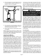
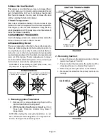
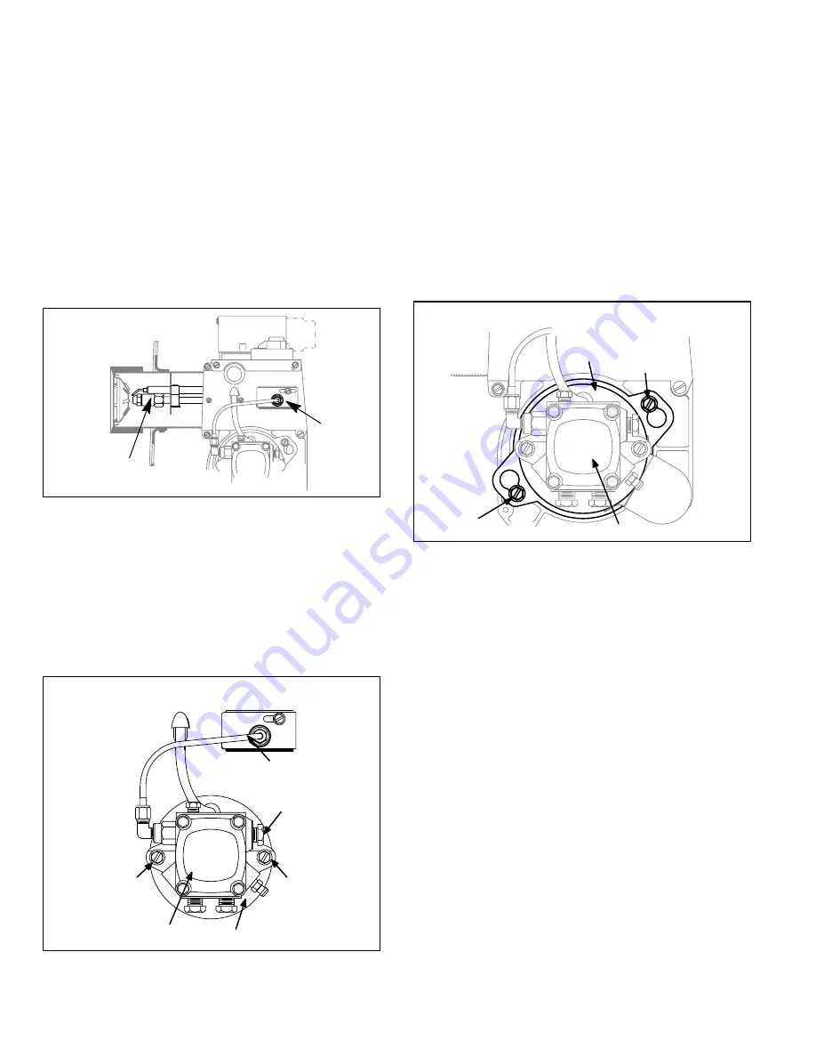
3 - Removing Gun Assembly
1 - Loosen the screw to the back access door until door
opens. See figures 21 and 22.
2 - Remove flare fitting nut on oil line at pipe adjusting plate
located on outside of blower housing.
3 - Remove nut connecting oil line to gun assembly oil
line. See figure 23.
4 - Remove gun assembly from air tube.
5 - Remove transformer leads.
NOTE-When reinstalling gun assembly, check and
set position and Z" dimension as shown in figure 18.
NOTE-When reconnecting gun assembly oil line, make
sure flat side of nut goes first.
FIGURE 23
GUN ASSEMBLY
Gun
Assembly
Remove
both nuts
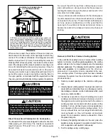
4 - Removing Oil Pump
1 - Disconnect supply line at pump and oil line at gun as
sembly.
2 - Loosen two bolts on sides of pump securing pump to
blower housing. See figure 24.
3 - Detach pump and motor shaft coupler from pump.
FIGURE 24
OIL PUMP
OIL PUMP MOTOR
BOLT
BOLT
SUPPLY LINE
INLET
OIL LINE GUN
ASSEMBLY ENTRANCE
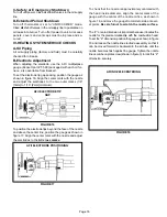
5 - Removing Motor / Combustion Air Blower
1 - Disconnect supply line at pump and oil line at gun as
sembly as shown in figure 24.
2 - If motor and blower wheel are to be removed away
from the burner, disconnect motor wiring harness
from the primary control. If the motor and blower
wheel only need to be removed to check and clean,
there is adequate wire in the motor wiring harness
without disconnecting.
3 - Loosen two bolts securing motor to blower hous
ing. Key hole slots are provided for easy removal.
See figure 25.
4 - Loosen allen set screw holding the blower wheel
onto the motor shaft and remove blower wheel.
FIGURE 25
COMBUSTION AIR MOTOR & WHEEL
BOLT
BOLT
BLOWER
MOTOR
PUMP
NOTE-When reinstalling blower wheel use the AFII multi
purpose gauge (Beckett part # T-500) to space the dis
tance from the back of the blower wheel to the face of the
motor (1/16" [2 mm]).
B-Removing Indoor Blower
1 - Turn off electric power to furnace.
2 - Remove blower access door.
3 - Remove two screws located in the front blower rails.
4 - Pull blower assembly out and place to the side.
VI-TYPICAL OPERATING CHARACTERISTICS
A-Blower Operation and Adjustment
NOTE- The following is a generalized procedure and
does not apply to all thermostat controls.
1 - Blower operation is dependent on thermostat con
trol system.
2 - Generally, blower operation is set at thermostat subbase
fan switch. With fan switch in ON position, blower oper
ates continuously. With fan switch in AUTO position,
blower cycles with demand.
3 - In all cases, blower and entire unit will be off when line
voltage is disconnected.


