Page 5
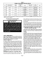
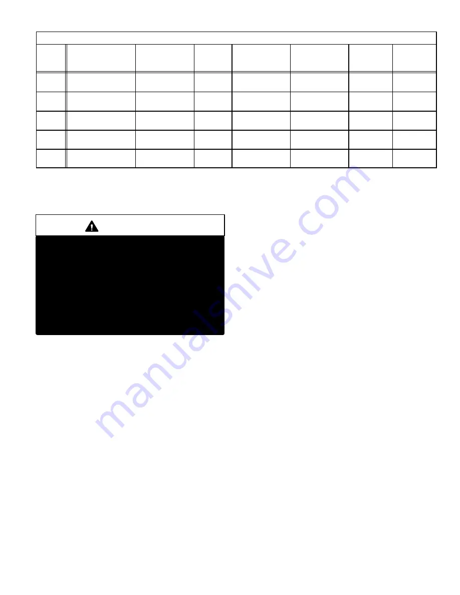
TABLE 1
FURNACE / BURNER SPECIFICATIONS
Unit
Lennox Burner
Part Number
Burner
Model
*Initial Air
Dial
Setting
Output
Nozzle Size
(Delevan)
Pump
Pressure
Head
70
35K74
AFII 85
3.0
57,000 BTU
(16.7 kW)
0.50 X 80
A
100 psig
(689.5 kPa)
FB0
105
35K75
AFII 85
4.0
84,000 BTU
(24.6 kW)
0.65 X 80
B
140 psig
965.3 kPa)
FB3
120
35K75
AFII 85
4.5
105,000 BTU
(30.8 kW)
0.75 X 80
B
140 psig
965.3 kPa)
FB3
140
35K76
AFII 150
6.0
112,000 BTU
(32.8 kW)
0.85 X 80
B
140 psig
965.3 kPa)
FB6
154
35K76
AFII 150
6.5
125,000 BTU
(36.6 kW)
1.00 X 80
B
140 psig
965.3 kPa)
FB6
*NOTE: The initial air dial setting is provided to get unit started. The air dial setting
MUST
be adjusted after startup to
achieve proper combustion.
CAUTION
Electrostatic discharge can affect electronic
components. Take precautions during furnace
installation and service to protect the furnace's
electronic controls. Precautions will help to avoid
control exposure to electrostatic discharge by
putting the furnace, the control and the techni
cian at the same electrostatic potential. Neutral
ize electrostatic charge by touching hand and all
tools on an unpainted unit surface, such as the
gas valve or blower deck, before performing any
service procedure.
ELECTROSTATIC DISCHARGE (ESD)
Precautions and Procedures
I-UNIT COMPONENTS
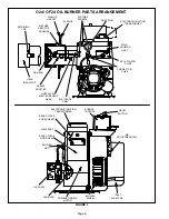
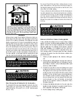
General parts orientation for the O24 and OF24 are shown in
figures 1 and 2 respectively. The O24 and OF24 burner, limit
switch and cleanout ports may be accessed by removing the
front access panel. The blower can be accessed in the O24
and OF24 by removing the blower access panel.
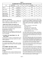
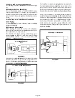
A-Burner (Figure 3)
The O24 and OF24 oil furnaces use the Beckett AFII burner.
The oil burner provides an atomized oil vapor mixed with the
correct proportion of air when it is ignited in the combustion
chamber. Oil burner minimum and maximum ratings are listed
on the unit nameplate. Proper air adjustment for these ratings
is achieved through the air adjustment dial. Set air dial to the
initial air dial setting (see table 1). After start up adjust air dial to
achieve proper combustion. Remember to tighten set screw on
air dial.
The AFII burner is available in five sizes with either a single
or two stage pump. Table 1 identifies the burners used in
Lennox units. Figure 3 shows the typical layout of the burner
assembly.
1-Combustion Air Blower / Pump Motor (B6)
The burner is activated by the primary control. A com
bustion air blower is mounted on the motor shaft. The
motor shaft also connects to the direct drive oil pump
through a coupler. The burner motor turns both the com
bustion air blower and the oil pump. The motor operates
at 3500 RPM.
Burner motors are overload protected. In the event of ex
cess motor temperature or current, the overload opens
to de-energize the motor. The overload automatically re
sets after temperature has returned to normal. Keep mo
tor clean to prevent starting switch from sticking. All AFII
motors are permanently lubricated. No further oiling is required.
2-Combustion Air Blower / Pump Fuse (F22)
(-140 and -154 CSA units only)
In the -140 and -154 Canadian units an in line fuse (F22) is
used between the line voltage from the blower control and
the blower / pump motor. The fuse is rated at 300 volts and
15 amps.
3- Pump
The O24 and OF24 oil furnaces use a single stage, 3450
RPM pump. A two stage pump is available as an option
(catalog # 65A44). The oil burner is shipped from factory
for use in a single line system. To convert the pump to a
two line system, install the bypass plug provided in the at
tached bag according to the accompanying instructions.
4-Burner Control (A3) & Transformer (T1)
The burner control, along with the matching cad cell, proves
flame and controls the burner. After the cad cell closes a circuit
to the burner control, the burner control de-energizes the safety
switch heater to allow the unit to operate normally. The burner
control allows 45 seconds for the cad cell to close. If the cad cell
remains open after the 45 second time frame, the burner con
trol locks out. The burner control must be manually reset by de
pressing the red reset button on top of the burner control.
Transformer (T1) is part of the burner control. T1 provides
24VAC to the low voltage components in the unit and to the
thermostat.
5-Cad Cell (R26)
Together the cad cell and the burner control prove flame.
The cad cell senses the presence of burner light (less re
sistance) to close a circuit to the burner control.
IMPORTANT-Burner should not be installed so it is ex
posed to direct sunlight or electric bulb light. If the cell
is exposed to light on start up, the burner will not oper
ate.


