Page 8
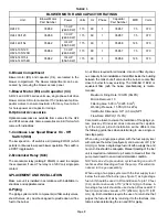
TABLE 3
BLOWER MOTOR AND CAPACITOR RATINGS
Unit
Blower Motor
Part Number
Power
Volts
Hz
Phase
Capacitor
Part Number
MFD
Volts
O24-70
35K59
1/3 HP
(248.6 KW)
115
60
1
35K57
7.5
370
O24-105/120
35K59
1/3 HP
(248.6 KW)
115
60
1
35K57
7.5
370
O24-140/154
35K62
3/4 HP
(559.5 KW)
115
60
1
35K58
12.5
370
OF24-105/120
OF24-105/120R
35K59
1/3 HP
(248.6 KW)
115
60
1
35K57
7.5
370
OF24-140/154
OF24-140/154R
35K62
3/4 HP
(559.5 KW)
115
60
1
35K58
12.5
370
C-Blower Compartment
Blower motor (B3) and capacitor (C4), are located in the
blower compartment. The blower compartment can be ac
cessed by removing the blower access panel.
1-Blower Motor (B3) and Capacitor (C4)
All O24 and OF24 series units use single phase belt drive
blower motors. All motors used are 115V permanent split ca
pacitor motors to ensure maximum efficiency. See table 3
for horsepower and capacitor ratings.
D-Optional Accessories
Optional accessories are available from Lennox for the O24
and OF24 series units. Some accessories are in kit form which
come with instructions.
1- Continues Low Speed Blower On - Off
Switch (S68)
The low speed on off switch is a kit (catalog # 67H91) which
permits continuous low speed blower operation. The switch is
a DPDT toggle switch.
2-Economizer Relay (K43)
The economizer relay (catalog # 65G40) is used to energize
the economizer if used. The relay is a 120V coil, single pole
contact.
II-PLACEMENT AND INSTALLATION
Make sure unit is installed in accordance with installation in
structions and applicable codes.
A-Piping
The piping system and it's components (oil filter, safety valves,
shutoff valves, etc.) must be designed to provide clean, air free
fuel to the burner.
An oil filter is required for all models.
Use an oil filter of gener
ous capacity for all installations. Install filter inside the building
between the tank shut-off valve and the burner. Locate filter
close to burner for easy servicing. The GAR-Ber 11BV-R or
equivalent filter (with the below specifications) is recom
mended.
Maximum Firing Rate: 10GPH (38LPH)
Micron Removal: 10
Filtering Area: 500 in.
2
(3225.8 cm
2
)
Working Pressure: 15 PSI (103.4 kPa)
Inlet/Outlet Dimension: 3/8" (9.5 mm) NPT
Flow Rate: 45GPH (171LPH)
Care must be taken to ensure the restriction of the piping sys
tem, plus any lift involved, does not exceed the capabili
ty of the oil pump. Each installation will be different. Use
the following guide lines when determining to use a single or
two stage pump.
When using a single pipe system with the fuel supply level
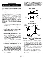
with or above the burner (see figure 6) and a vacuum of 6" (152
mm) Hg or below, a single stage fuel unit with a supply line and
no return line should be adequate. Manual bleeding of the fuel
unit is required on initial start up. Failure to bleed air from the
pump could result in an air lock/oil starvation condition.
NOTE-As an extra precaution, cycle heating on and off
ten times after bleeding air from the pump. This will elimi
nate air in the gun assembly.
When using a two pipe system with the fuel supply level
below the level of the burner (see figure 7) a single stage
fuel unit should be used in lift conditions of up to 10 feet
(3 m) and/or a vacuum of 10" (254 mm) Hg or below. A
two stage fuel unit should be used when lift exceeds 10
feet (3 m) and/or a vacuum of 10" (254 mm) Hg to 15" (381
mm) Hg. Both conditions require the use of a return line that
purges the fuel unit of air by returning it to the fuel tank. Use
table 4 when determining the run and lift for piping.


